Electronic cigarette

a technology of electronic cigarettes and flavor components, which is applied in the field of electronic cigarettes, can solve the problems of not being able to obtain sufficient flavor components at the beginning of simulated smoking, long time is required for the flavor generating medium to generate a sufficient amount of flavor components, and not being able to provide the feeling of a cigar

Inactive Publication Date: 2005-01-27
SEIKO EPSON CORP
View PDF4 Cites 1053 Cited by
  • Summary
  • Abstract
  • Description
  • Claims
  • Application Information

AI Technical Summary

Benefits of technology

[0043] Since this makes it possible to generate simulated smoke from the smoke generating means, to stop the generating of smoke, and to adjust the

Problems solved by technology

In a smoking simulator having such a configuration, however, since it takes time to increase the temperature of the flavor generating medium, a long time is required for the flavor generating medium to generate a sufficient amount of flavor components.
Thus, a sufficient amount of flavor components can not be obtained at the beginning of simulated smoking, and a feeling similar to that of a cigarette cannot be provided from the beginning of simulated smoking.
Since the amount o

Method used


Image

  • Electronic cigarette
  • Electronic cigarette
  • Electronic cigarette

Examples


first embodiment

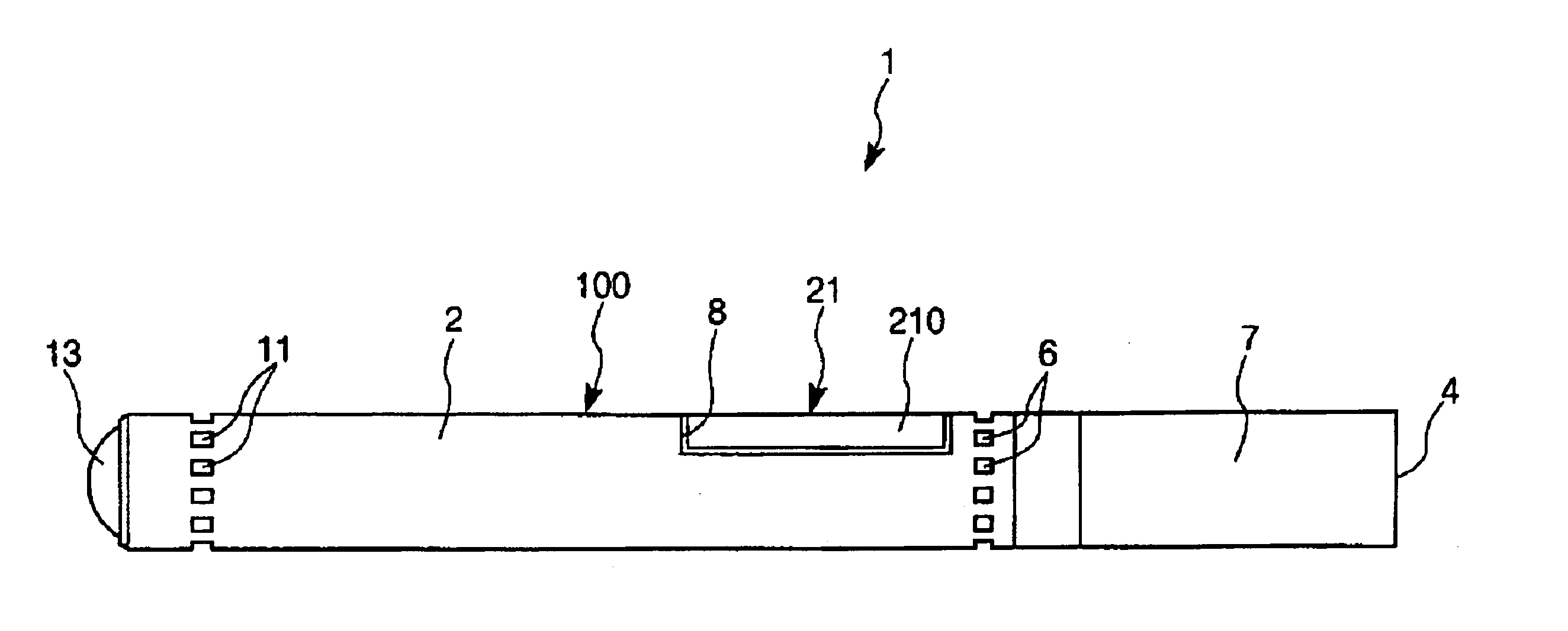
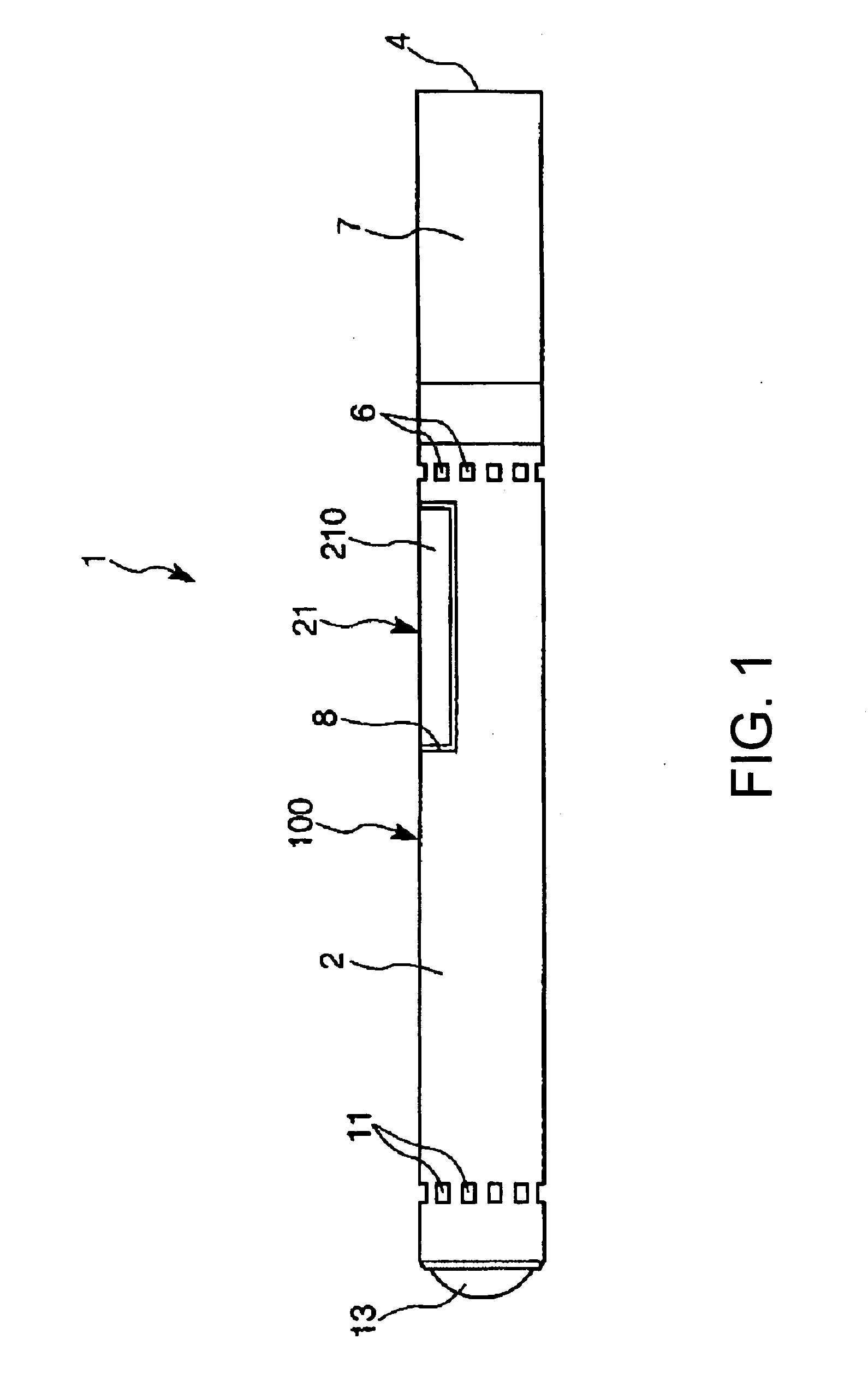
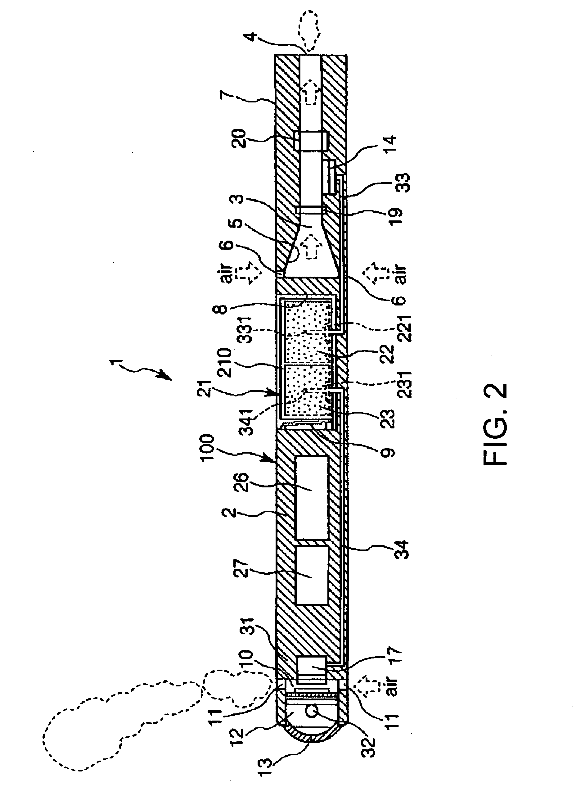
[0054] FIGS. 1 to 5 show an electronic cigarette according to the invention. FIG. 1 is a plan view showing the electronic cigarette as a whole; FIG. 2 is a sectional view of FIG. 1; FIG. 3 is an enlarged view of a part of FIG. 2; FIG. 4 is a sectional view showing an example of a configuration of ejection means; and FIG. 5 is a block diagram of the electronic cigarette.

[0055] For convenience in description, the left side and the right side in FIGS. 1 and 2 will be described as “tip end” and “base end”, respectively.

[0056] As shown in FIGS. 1 and 2, an electronic cigarette 1 has a cigarette main body 100 having a round bar-like (bar-like) or cylindrical configuration as a whole and a cartridge 21 having a containing portion containing a liquid flavor generating medium.

[0057] The cigarette main body 100 has a casing 2, first ejection means (ejection means) 14 which ejects droplets of the flavor generating medium into the casing 2 and second ejection means (smoke generating means) 17...

second embodiment

[0113]FIGS. 6 and 7 show an electronic cigarette according to the invention. FIG. 6 is an enlarged illustration of a part of the same, and FIG. 7 is a block diagram of the electronic cigarette.

[0114] An electronic cigarette 1 according to the second embodiment will now be described, the description being focused on differences from the above-described first embodiment and omitting items that are identical between them.

[0115] As shown in FIG. 6, atomizing means 18 for atomizing (refining) droplets of a flavor generating medium ejected from the nozzle 16 of each ejection head 15 of the first ejection means 14 is provided facing the nozzles 16. Although not shown, atomizing means 18 for atomizing (refining) droplets of a flavor generating medium ejected from the nozzle 16 of each ejection head 15 of the second ejection means 17 is similarly provided facing the nozzles 16. As shown in FIG. 7, the control means 27 has an atomizing means driving circuit 30 incorporating a circuit for dri...


PUM


Abstract

An electronic cigarette is provided. The electronic cigarette includes a casing having an inhalation hole and a substantially cylindrical configuration, ejection means (first ejection means) provided in the casing and at least one ejection head. Pressure in a cavity filled with a liquid flavor generating medium is changed by driving an actuator to eject the flavor generating medium as droplets from a nozzle in communication with the cavity. Control means provided in the casing controls the driving of the ejection means.

Description

RELATED APPLICATIONS [0001] This application claims priority to Japanese Patent Application No. 2003-198701 filed Jul. 17, 2003 which is hereby expressly incorporated by reference herein in its entirety. BACKGROUND [0002] 1. Technical Field to which the Invention Belongs [0003] The present invention relates to an electronic cigarette. [0004] 2. Related Art [0005] Recently, various types of smoking simulators for tasting a flavor resembling that of a cigarette without burning a cigarette have been proposed. [0006] For example, smoking simulators have been proposed, in which a heating element and solid flavor generating medium are provided in a heat-insulating tube and in which the heat-insulating tube and a power supply of the heating element are wrapped in fine quality wrapping paper and formed like a cigarette (for example, see Japanese Patent Laid-Open No. JP-A-3-232481). [0007] In a smoking simulator having such a configuration, electrical energy is supplied from the power supply...

Claims


Application Information

Patent Timeline
IPC IPC(8): A24F40/10A24F40/48A24F40/50A24F40/60A61M11/04A61M15/02A61M15/06
CPCA24F47/002A61M15/02A61M15/025A61M11/042A61M15/06A61M11/005A61M2205/14A24F40/60A24F40/10A24F40/50A24F40/48
Inventor KATASE, MAKOTO
Owner SEIKO EPSON CORP
Why Eureka
Try Eureka