Packaging system

a packaging system and packaging technology, applied in the field of packaging systems, can solve the problems of affecting the efficiency of the rotary vacuum packaging device, affecting the sealing properties of the packaged body, and excessive space inside the bags

Active Publication Date: 2005-02-03
FURUKAWA MFG
View PDF26 Cites 48 Cited by
  • Summary
  • Abstract
  • Description
  • Claims
  • Application Information

AI Technical Summary

Benefits of technology

[0009] If the resistance of a bag does act on the opening and closing bars, then the pushing bar pushes the item to be packaged mounted on the waiting station, inside the bag in the pressure resistant chamber, via the beak-shaped hopper, and immediately thereupon, the pushing bar is returned to its original position, together with the beak-shaped hopper, leaving only the opening and closing bars behind. The opening and closing bars then open out for a second time, thereby tensioning the mouth of the bag, and with the mouth of the bag in this tensioned state, it is conveyed to a sealing platform by a pair of clamps. Therefore, when the mouth of the bag is heated and sealed by the sealing bars, in the rotary path of the pressure resistant chambers, a seal without any wrinkles is produced and hence the tight vacuum seal of the bag is preserved.

Problems solved by technology

However, with a vacuum packaging device of this kind, too, excessive space occurs inside the bags when packaged objects are of indefinite shapes.
However, a distortion or slack is caused to occur at the mouth of the bag during transportation, which impairs the vacuum sealing properties of the packaged body.
If such distortion or slack of the bag is removed while the bag is on the sealing platform, the efficiency of the rotary vacuum packaging device is adversely affected.

Method used


Image

  • Packaging system
  • Packaging system
  • Packaging system

Examples


Embodiment Construction

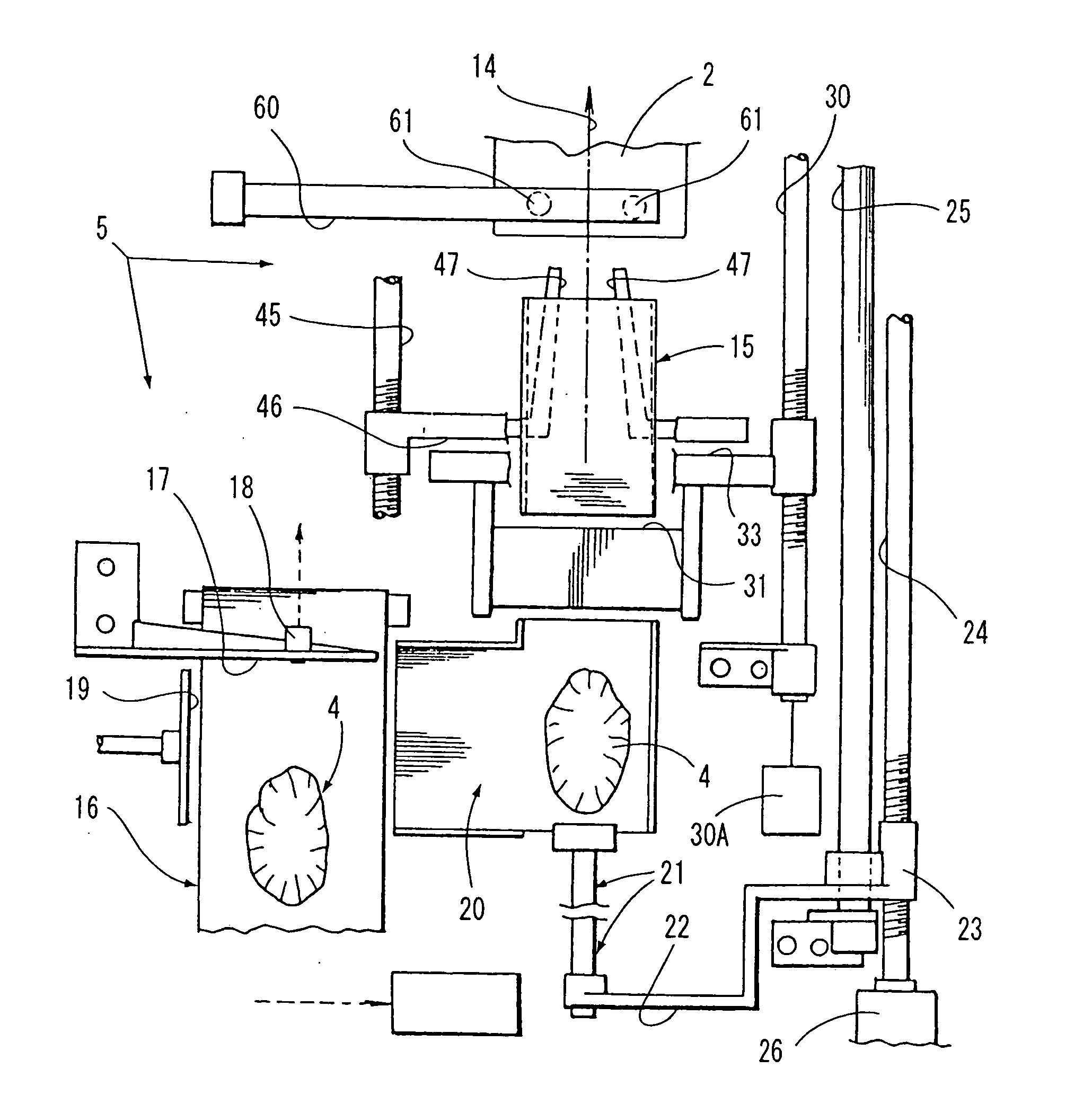
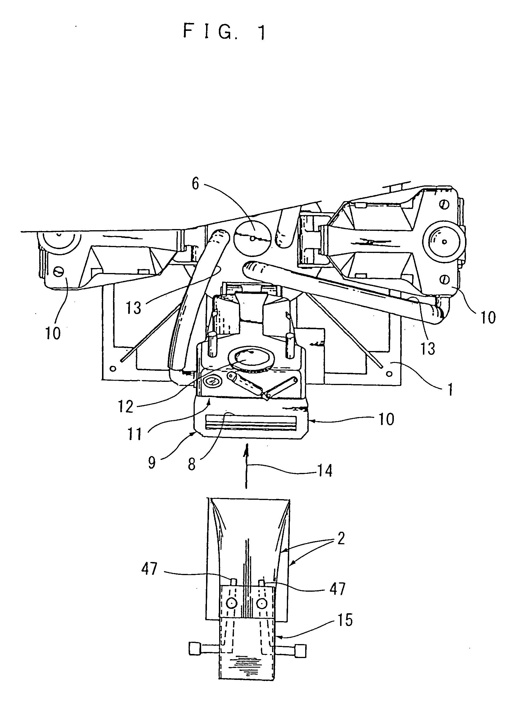
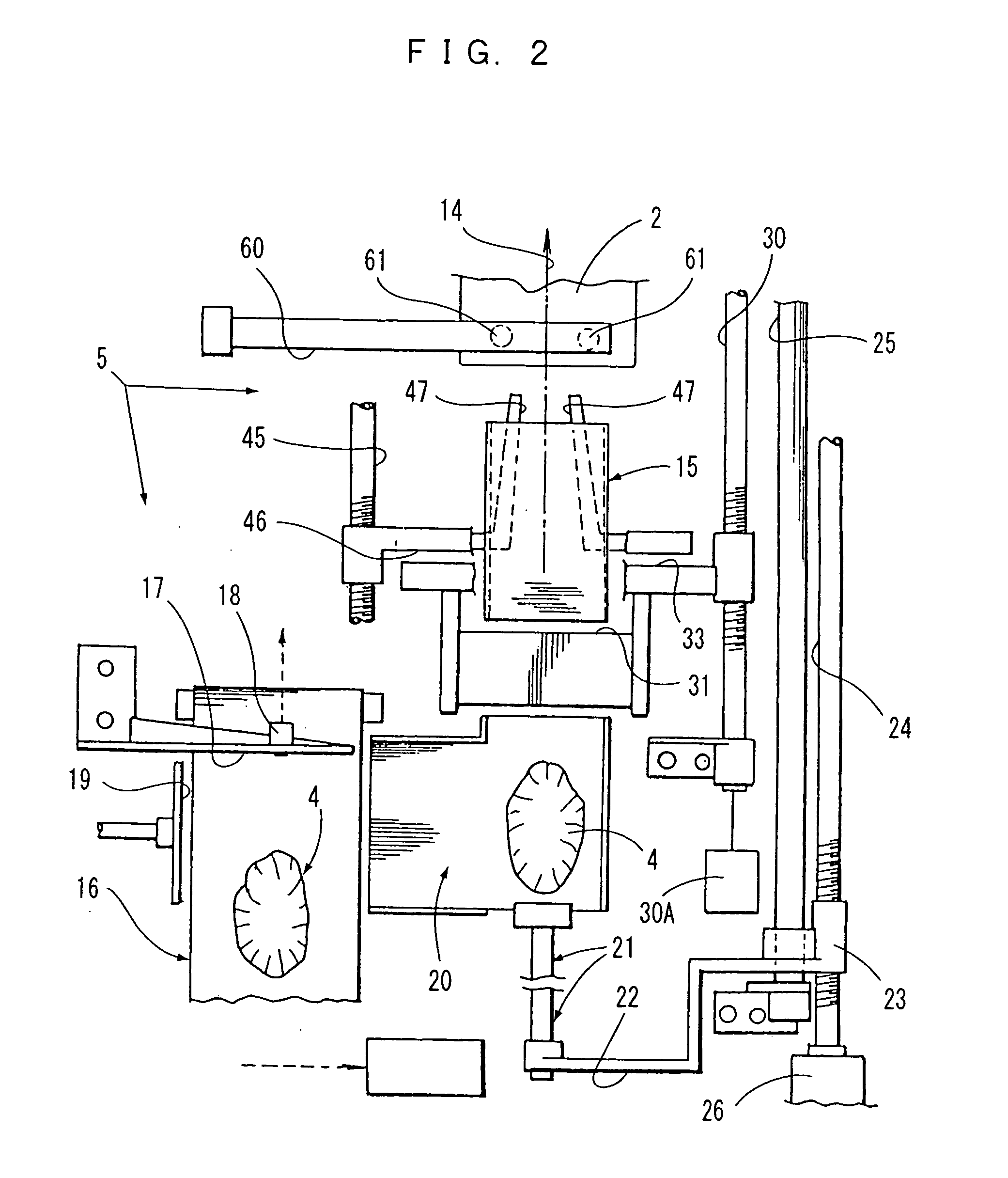
[0026]FIG. 1 is a partial plan view of a rotary vacuum packaging device, and FIG. 2 is a plan view of a device for supplying an item to be packaged and a bag, to the vacuum packaging device. The packaging system which is illustrated in a separated fashion in these two diagrams comprises a rotary vacuum packaging device 1 which seals a bag containing an item to be packaged, under vacuum conditions, thereby creating a vacuum packaged product, and respective conveyance mechanisms 5 for supplying empty bags to the vacuum packaging device 1 and accommodating the items to be packaged 4 inside the bags 2.

[0027] In FIG. 1, the rotary vacuum packaging device 1 is shown in a partial fashion, due to considerations of space, but this vacuum packaging device 1 comprises four pressure resistant chambers 10 which are rotated intermittently, at positions 90° apart, by means of the driving force of a centrally positioned main axle 6. The respective pressure resistant chambers 10 are each equipped w...


PUM

PropertyMeasurementUnit
pressureaaaaaaaaaa
resistanceaaaaaaaaaa
air pressureaaaaaaaaaa

Abstract

A packaging system is provided which supplies an item to be packaged and a bag covering the item to a pressure resistant chamber, for a heat sealing mechanism which arrives at a certain time interval, in accordance with the circulation timing of each sealing mechanism. The packaging system includes means for causing a beak-shaped hopper and a pair of opening and closing bars, to move back and forth in unison along a main travel path leading to a rotary vacuum packaging device, means for extending and supporting the opening section of an uppermost packaging bag, and conveying same into a pressure resistant chamber of the vacuum packaging device, means for causing a waiting station to move following the conveyance movement of the beak-shaped hopper into a pressure resistant chamber, and means for opening the opening and closing bars towards either side immediately after the bag has been conveyed into the pressure resistant chamber.

Description

FIELD OF THE INVENTION [0001] The present invention relates to a packaging system for supplying bags for accommodating therein items to be packaged, to respective pressure resistant chambers provided with a rotary type vacuum packaging apparatus, in such a manner that they match the circulation pitch of the pressure resistant chambers. BACKGROUND OF THE INVENTION [0002] JP10-81310A describes a system in which a band-shaped film is formed into a tube-shape which surrounds the circumference of respective blocks of meat which move along a linear travel path, at equidistant intervals. The tube film into which a respective block of meat has been packaged is cut successively and separated, and each individual packaging bag containing a block of meat is supplied successively to a pressure resistant chamber of a rotary vacuum packaging device, by means of a belt conveyor. By means of this system, since a control is provided which causes the interval between the respective blocks of meat hav...

Claims


Application Information

Patent Timeline
Patent Type & Authority Applications(United States)
IPC IPC(8): B65B5/04B65B25/06B65B31/02B65B57/02
CPCB65B5/045B65B25/065B65B57/02B65B39/02B65B43/28B65B31/046
Inventor KUJUBU, EITAROKONDO, HIROSHIKUDO, WATARU
Owner FURUKAWA MFG
Why Eureka
Try Eureka