Automatic range up-shift control and method of operation

a control system and automatic technology, applied in the direction of conjoint control, mechanical equipment, transportation and packaging, etc., can solve the problem of range up-shifts occurring before the vehicle speed becomes unacceptably high, and achieve the effect of preventing and/or minimizing undue wear and/or damage to the range synchronizer and minimizing undue damag

Inactive Publication Date: 2005-02-03
EATON CORP
View PDF34 Cites 5 Cited by
  • Summary
  • Abstract
  • Description
  • Claims
  • Application Information

AI Technical Summary

Benefits of technology

[0010] In accordance with the present invention, the drawbacks of the prior art are minimized or overcome by the provision of a range shift control for a computer-assisted mechanical transmission system that will sense vehicle operating conditions and will avoid unacceptable range up-shifts to prevent and / or minimize undue wear and / or damage to the high speed range synchronizer during a range up-shift. This is accomplished by causing range up-shifts to occur before the vehicle speed becomes unacceptably high. A range up-shift to a high range is automatically made if (i) a range up-shift has not been already initiated, (ii) a position of a shift lever is in a low range neutral position, and (iii) a vehicle speed is greater than a predetermined value, thereby preventing and / or minimizing undue wear and / or damage to the range synchronizer during a range up-shift. If a range upshift has already been initiated, then established shift protocols are invoked to complete the up-shift. Otherwise, the system continues to monitor the specified conditions to determine the need for an up-shift.

Problems solved by technology

This is accomplished by causing range up-shifts to occur before the vehicle speed becomes unacceptably high.

Method used


Image

  • Automatic range up-shift control and method of operation
  • Automatic range up-shift control and method of operation
  • Automatic range up-shift control and method of operation

Examples


Embodiment Construction

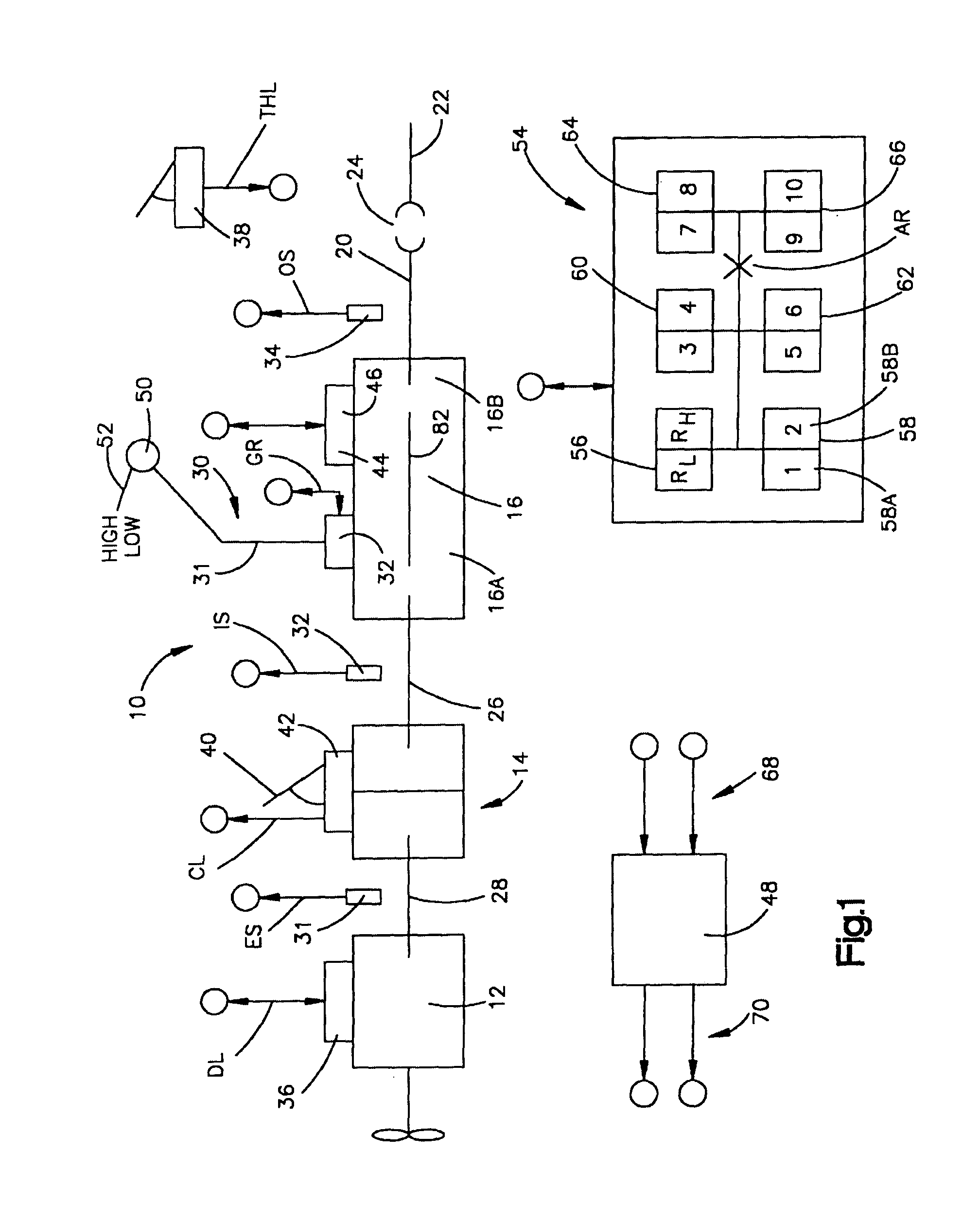
[0018] A computer-assisted (i.e., microprocessor-based, controller-assisted) vehicular compound mechanical transmission system 10, particularly well suited to utilize the range shift control of the present invention, may be seen by reference to FIGS. 1-4B.

[0019] System 10 is of the type commonly utilized in heavy-duty vehicles, such as the conventional tractors of tractor / semi-trailer vehicles, and includes an engine, typically a diesel engine 12, a master friction clutch 14 contained within a clutch housing, a multiple-speed compound transmission 16, and a drive axle assembly (not shown). The transmission 16 includes an output shaft 20 drivingly coupled to a vehicle drive shaft 22 by a universal joint 24 for driving the drive axle assembly. The transmission 16 is housed within a transmission housing to which is directly mounted the shift tower of the shift lever assembly 30. The present system is equally applicable to remotely mounted shift levers, as are used in cab-over-engine t...


PUM


Abstract

A control for enhanced range shifting in a computer (48) assisted vehicular compound transmission having a main section (16A) shifted by a manually operated shift lever (31) and a range section (16B) shifted in response to operation of a range shift selector, such as sensing shift lever (31) passing through a predetermined actuation point (AR) in the shift pattern. During a compound up-shift, if the vehicle reaches a speed greater than a predetermined value during a coasting condition and the shift lever is in a low range neutral position, then the range section up-shift is automatically completed without undue wear or damage to the range section synchronized clutch (130). It is emphasized that this abstract is provided to comply with the rules requiring an abstract that will allow a searcher or other reader to quickly ascertain the subject matter of the technical disclosure. It is submitted with the understanding that it will not be used to interpret or limit the scope or meaning of the claims. 37 CFR 1.72(b).

Description

BACKGROUND OF THE INVENTION [0001] 1. Field of the Invention [0002] The present invention relates to a control system / method for controlling range shifting in a compound transmission having a lever-shifted main section and a range section shifted by a range section actuator for selectively positioning a synchronized double-acting positive clutch. The transmission may also have a splitter section. In particular, the present invention relates to controlling range shifting in a lever-shifted, partially automated vehicular transmission system having a microprocessor-based controller for controlling the operation of a range shift actuator and / or an engine fuel control. [0003] 2. Description of the Related Art [0004] Controller-assisted, manually shifted transmission systems are known in the prior art, as may be seen by reference to U.S. Pat. Nos. 5,582,558; 5,755,639; 5,766,111; 5,791,189; 5,974,906; 5,989,155 and 6,015,366, the disclosures of which are incorporated herein by reference. ...

Claims


Application Information

Patent Timeline
Patent Type & Authority Applications(United States)
IPC IPC(8): F16H61/02F16H61/70
CPCF16H61/0213F16H61/702Y10T477/60Y10T74/1926F16H2300/18
Inventor STINE, ALAN C.LEMON, MICHAEL E.WADAS, DAVID L.WANG, YEIDEI
Owner EATON CORP
Why Eureka
Try Eureka