
Secure interface cradle for pocket personal computer device

Active Publication Date: 2005-02-10
CARNEVALI JEFFREY D
View PDF24 Cites 23 Cited by
  • Summary
  • Abstract
  • Description
  • Claims
  • Application Information

AI Technical Summary

Benefits of technology

[0006] The spring-loaded clamping mechanism permits such a pocket PC or other hand-held or mobile device to be easily and securely

Problems solved by technology

However, current mounting platforms may be inefficient for effectively securely releasably cradling

Method used


Image

  • Secure interface cradle for pocket personal computer device
  • Secure interface cradle for pocket personal computer device
  • Secure interface cradle for pocket personal computer device

Examples


Example

[0035] In the Figures, like numerals indicate like elements.

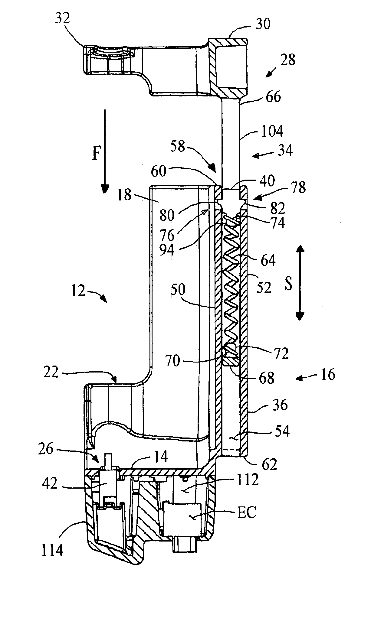
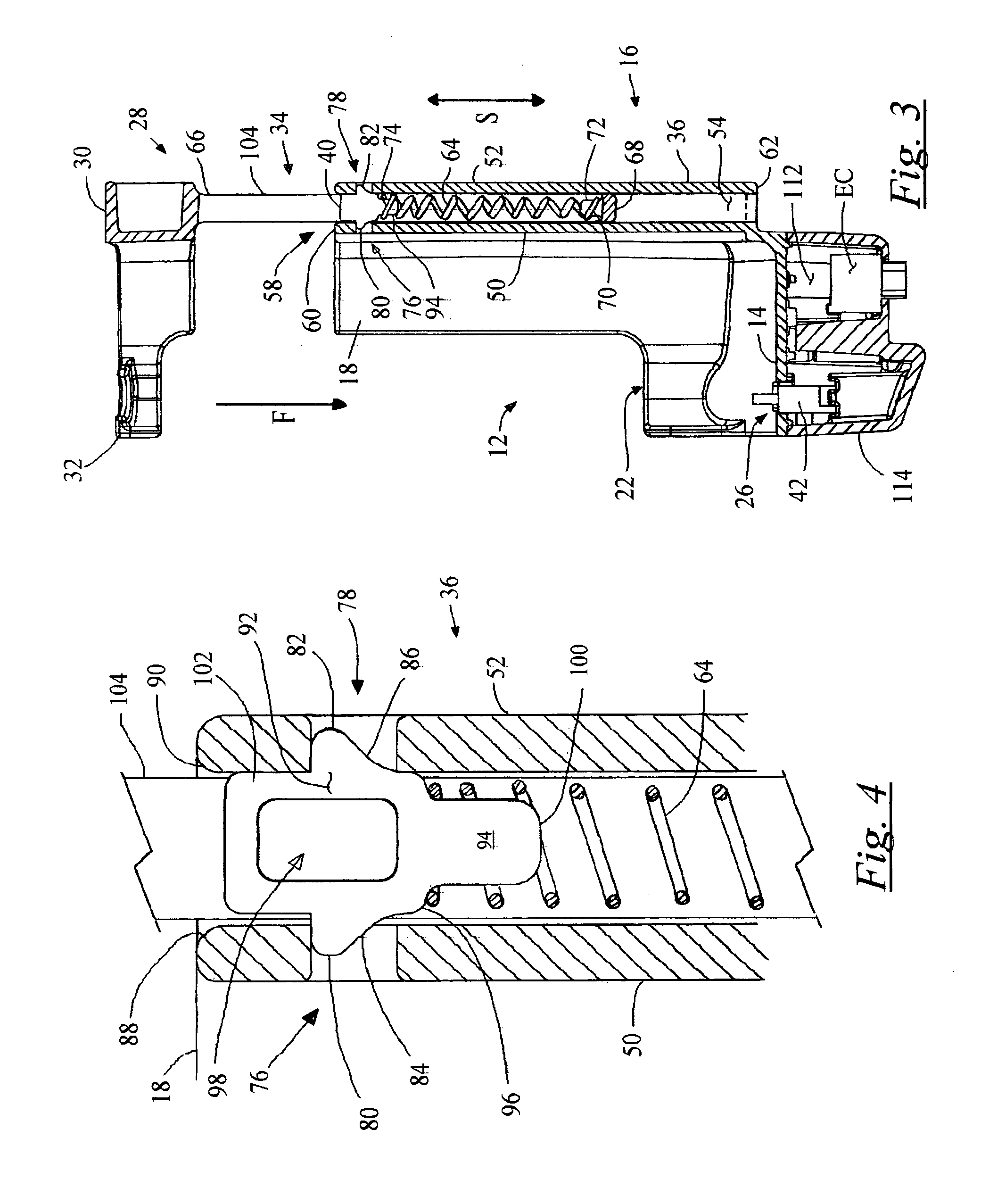
[0036] The present invention is a spring-load clamping mechanism formed by a pair of resiliently flexible walls spaced apart a substantially constant distance and having an opening formed therebetween. A compression spring is sized to be compressed between the spaced apart walls. A clamp is provided having a drive portion extending from a jaw portion, the drive portion is sized to slidingly fit between the spaced apart walls and includes structure that is adapted to engage a first end of the spring, the spring engagement structure is spaced away from the jaw portion. A locking key is structured to substantially permanently interlock with one or more of the spaced apart walls and to engage a second end of the spring.

[0037] Accordingly, the locking key is formed with one or more detents that project from a body portion; and at least one of the resiliently flexible walls is formed with a notch positioned adjacent to the open...


PUM


Abstract

A secure clamping mechanism formed with two spaced apart surfaces; a resiliently compressible biasing member positioned between the two spaced apart surfaces; a clamp having a drive shaft that is structured to be slidingly engaged between the two spaced apart surfaces; and an interference means for engaging the biasing member between the drive portion and at least one of the spaced apart surfaces.

Description

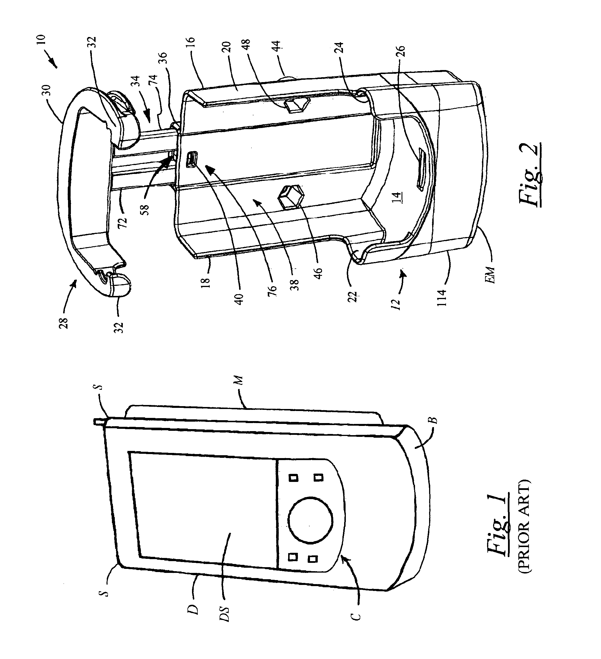
FIELD OF THE INVENTION [0001] The present invention relates to a mounting apparatus for an electronic device, and in particular to mounting apparatuses for securely releasably cradling and electrically interfacing a pocket-sized personal computer and other mobile electronic devices. BACKGROUND OF THE INVENTION [0002] Mounting platforms are generally well-known for securely cradling and electrically interfacing hand-held pocket-sized personal computers, commonly referred to as “pocket PCs,” and other mobile electronic devices, such as cellular telephones, mobile global positioning system (GPS) receivers, Personal Digital Accessories (PDAs) and other mobile electronic devices of the type generally illustrated in FIG. 1. [0003] One such mounting platform is presented in U.S. Pat. No. 6,427,959, entitled MOUNTING BRACKET FOR AN ELECTRONIC DEVICE, issued Aug. 6, 2002, to Kalis, et al., which is incorporated herein by reference, which includes a cradle adapted for being releasably secured...

Claims


Application Information

Patent Timeline
IPC IPC(8): A44B99/00A45F5/00B60R11/02F16M13/02G06F1/16
CPCA45C2011/002A45F5/00A45F5/02A45F2200/0516B60R11/0241F16M13/02Y10T24/1382G06F1/1632F16M11/041F16M13/00F16M13/022Y10T24/44581Y10T24/13G06F1/163
Inventor CARNEVALI, JEFFREY D.
Owner CARNEVALI JEFFREY D
Learn More