Cable ties having innate connection compatibility with mounting plates

a technology of innate connection and mounting plate, applied in the field of cable ties, can solve the problems of inability to group with the pre-existing closely-mounted mounting plate, and difficulty is not resolvabl

Inactive Publication Date: 2005-02-10
MEDCOUNT SYST L L C
View PDF10 Cites 5 Cited by
  • Summary
  • Abstract
  • Description
  • Claims
  • Application Information

AI Technical Summary

Problems solved by technology

This practice presents evident difficulties in possible disruption of pre-existing cable bundlings supported on the mounting plate and in electrician time in effecting the disassembly of the mounting plate from the parent structure and reassambly following the binding of the cable ties to the mounting plate.
In those instances in which the mounting plates are not removable from their parent structures, i.e., are riveted or otherwise permanently secured to the mounting plate, the difficulty is not resolvable and additions of cable tie encircled conductor groupings to the pre-existing closely-mounted mounting plate are not attainable.

Method used


Image

  • Cable ties having innate connection compatibility with mounting plates
  • Cable ties having innate connection compatibility with mounting plates

Examples


Embodiment Construction

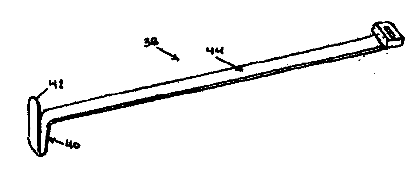
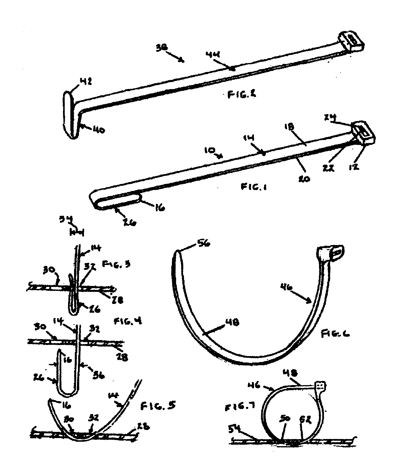
[0016] Referring to FIG. 1, cable tie 10 includes a head portion 12 and a tail portion 14 contiguous with head portion 12 and extending to tail portion free end 16. Serrations (not shown) are formed on either or both of top and bottom sides 18 and 20 of tail portion 14. Head portion 12 includes pawl 22 extending into through passage 24. As is known, pawl 22 may be a plastic member integrally formed with cable tie 10 or may be a metal member.

[0017] Cable tie 10 is a molded plastic member, the making mold being constructed to impart undulation 26 to tail portion 14 at tail portion free end 16.

[0018] Referring to FIG. 3, mounting plate 28 defines apertures 30 and 32 extending therethrough. Undulation 26 of tail portion 14 is inserted into aperture 32, which is of a cross-dimension 34 less than the cross-dimension 36 of undulation 26. Undulation 26 is accordingly cross-wise compressed in the course of the insertion, as shown in a first stage of assembly of FIG. 3.

[0019] Referring to ...


PUM


Abstract

Cable ties have configuration which self-urges free ends of the cable ties to emerge from mounting plates after the free ends of the cable ties are inserted into disposition into a limited space existing between the mounting plates and parent structure to which the mounting plates are secured.

Description

FIELD OF THE INVENTION [0001] This invention relates generally to cable ties and pertains more particularly to cable ties configured for use with mounting plates closely mounted on parent support structure. BACKGROUND OF THE INVENTION [0002] In various instances, it is desirable to bind cable ties upon a mounting plate which is so closely mounted on parent structure as to deny user access to the undersurface of the mounting plate. In these instances, it is necessary to remove the mounting plate from its parent structure. This practice presents evident difficulties in possible disruption of pre-existing cable bundlings supported on the mounting plate and in electrician time in effecting the disassembly of the mounting plate from the parent structure and reassambly following the binding of the cable ties to the mounting plate. [0003] In those instances in which the mounting plates are not removable from their parent structures, i.e., are riveted or otherwise permanently secured to the...

Claims


Application Information

Patent Timeline
Patent Type & Authority Applications(United States)
IPC IPC(8): F16L3/233
CPCY10T24/1498F16L3/233
Inventor LOGAN, MAURUS
Owner MEDCOUNT SYST L L C
Why Eureka
Try Eureka