Dynamic seating system for personal mobility vehicle

a seating system and personal mobility technology, applied in the field of land vehicles, can solve the problems of reduced blood circulation to that tissue, vehicle users tend to fight against the seating system or feel restricted, and personal mobility vehicles are often subject to damag

Inactive Publication Date: 2005-02-10
SUNRISE MEDICAL HHC INC
View PDF23 Cites 40 Cited by
  • Summary
  • Abstract
  • Description
  • Claims
  • Application Information

AI Technical Summary

Problems solved by technology

Blood circulation to that tissue will be reduced, and ulcers or other problems can result.
Vehicle users tend to fight against the seating system or feel restricted due to the rigidity.
As a result, the personal mobility vehicle is often subjected to damage.

Method used


Image

  • Dynamic seating system for personal mobility vehicle
  • Dynamic seating system for personal mobility vehicle
  • Dynamic seating system for personal mobility vehicle

Examples


Embodiment Construction

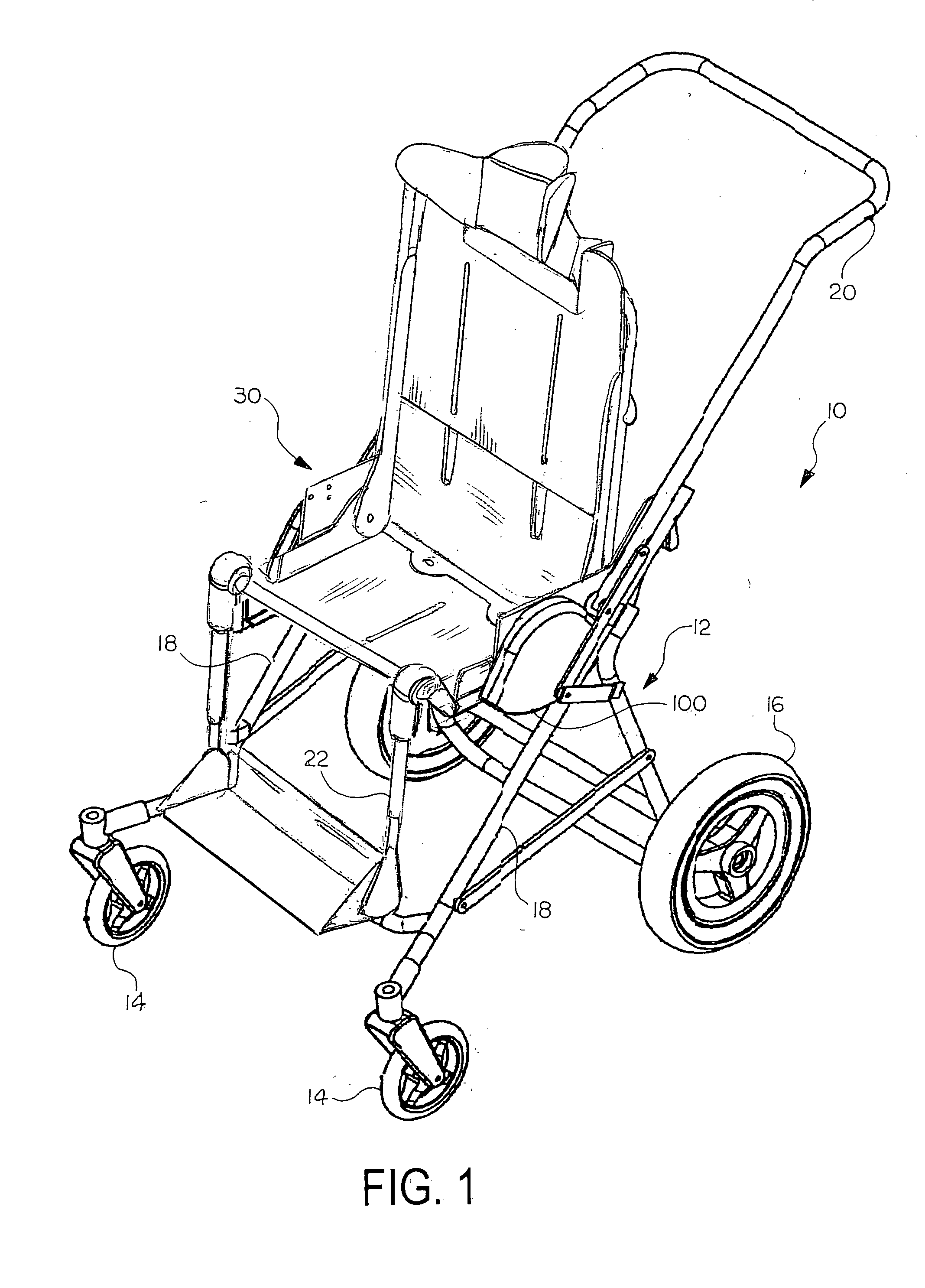
[0020] Referring now to the drawings, there is illustrated in FIG. 1 a personal mobility vehicle, generally indicated at 10, which may be in the form of a wheelchair, a stroller, or the like. The vehicle comprises a base 12, which is mounted for movement on front caster wheels 14 and rear wheels 16. The base 12 includes a frame 18, which may include welded or bolted members, some of which may be tubular. The frame 18 may extend upwardly to form a handle 20. A leg support 22 can be provided. The base 12 supports a seating system, generally indicated at 30.

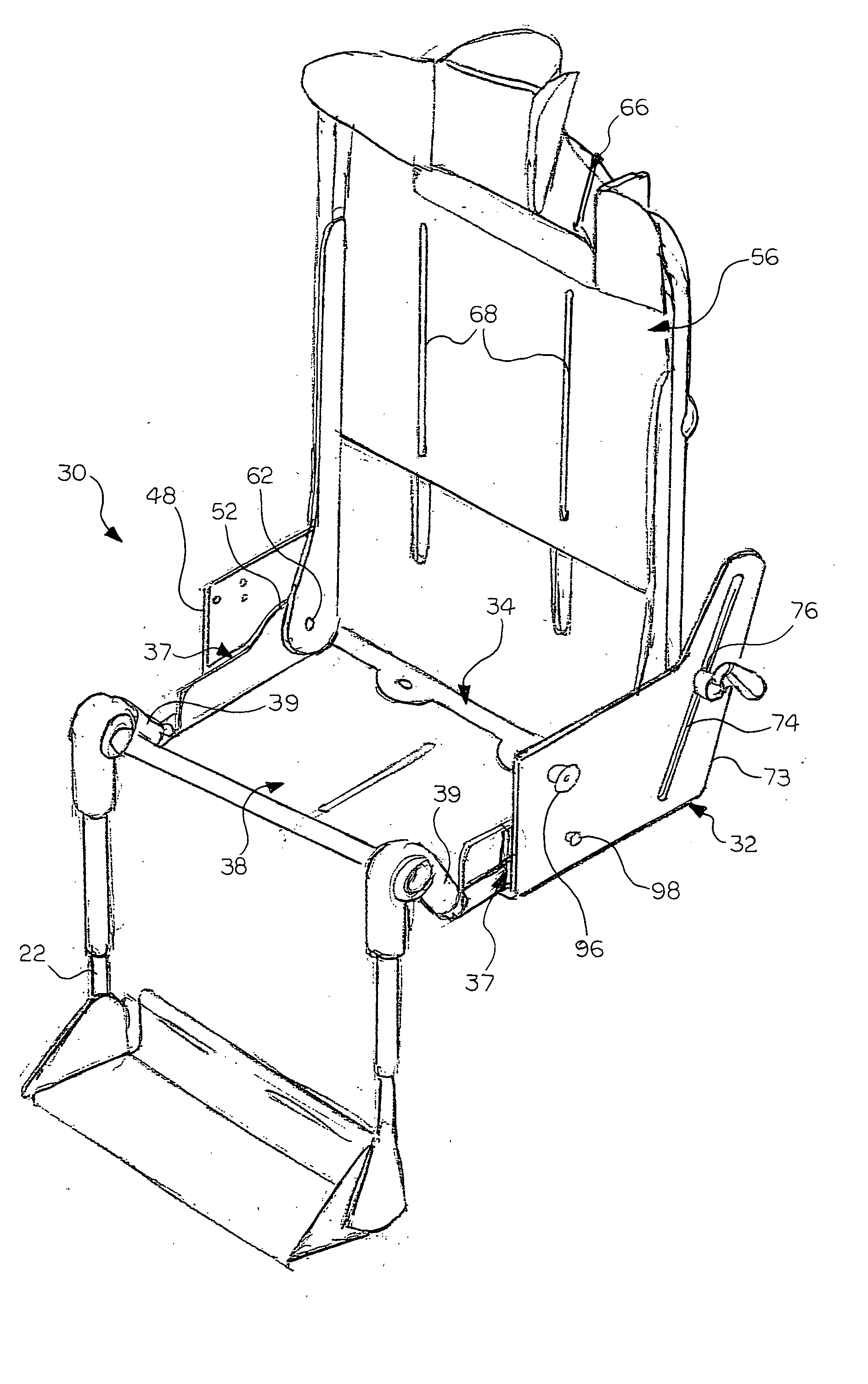
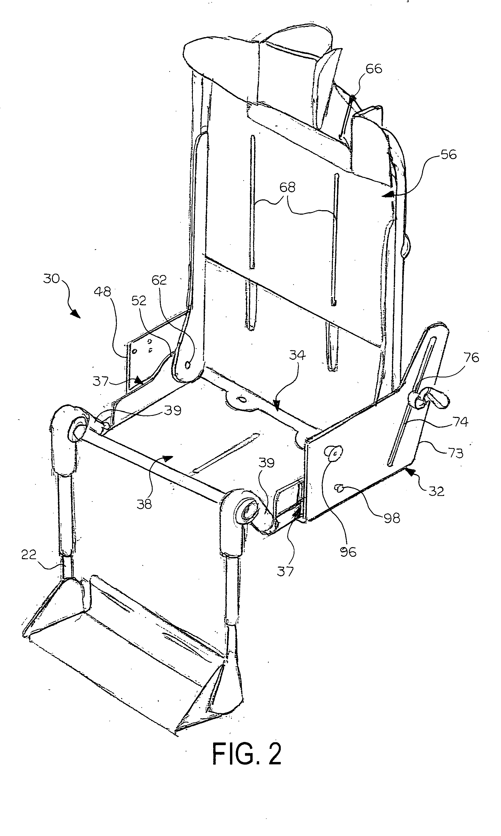
[0021] As shown in FIGS. 2-4, the seating system 30 of the invention may include a seating shell base 32, into which may be nested or positioned an inner seat tray 34. The seating shell base 32 is attached to and supported by the base 12. The inner seat tray 34 is secured to the seating shell base 32 in a manner that allows the inner seat tray 34 to slide forward and rearward with respect to the seating shell base 32. An optional s...


PUM


Abstract

A dynamic seating system includes a seat tray that is positioned within a base and mounted for forward and rearward sliding movement with respect to the base. A biasing element is connected relative to the base and the seat tray for biasing the seat tray rearward relative to the base.

Description

CROSS REFERENCE TO RELATED APPLICATIONS [0001] This application is a continuation-in-part of pending application Ser. No. 10 / 403,558 filed May 31, 2003, assigned to the assignee of this application, and incorporated herein by reference.BACKGROUND OF INVENTION [0002] This invention relates in general to land vehicles and, more particularly, to personal mobility vehicles. Most particularly, this invention relates to a seating system for personal mobility vehicles. [0003] Personal mobility vehicles, such as wheelchairs and strollers, often have a fixed seat consisting of a seating surface and a back frame. The seat and back frames are typically mounted on a base, which, for most personal mobility vehicles, supports two rear drive wheels and two front caster wheels. The personal mobility vehicle can be either manual driven, or power driven, in which case, the drive wheels will be motorized. The seating surface is usually either horizontal or slightly tilted back, with the front edge of ...

Claims


Application Information

Patent Timeline
Patent Type & Authority Applications(United States)
IPC IPC(8): A47C7/00A61G5/08A61G5/10A61G5/12B62B9/12
CPCA61G5/045B62B9/142A61G5/1064A61G5/1067A61G5/1075A61G5/12A61G2005/0866A61G2005/0883A61G2005/0891A61G2005/121A61G2005/128B62B9/104B62B9/18B62B9/00A61G5/08A61G5/0866A61G5/0883A61G5/0891A61G5/121A61G5/128
Inventor HANSON, WAYNE H.PHELPS, WILLIAM B.SANFORD, STEPHEN M.
Owner SUNRISE MEDICAL HHC INC
Why Eureka
Try Eureka