
Compression connector for coaxial cable and method of installation

a technology of compression connector and coaxial cable, which is applied in the direction of connections, basic electric elements, electric devices, etc., can solve the problems of achieve the effect of reducing the cross section and tight frictional engagement between the connector and the cabl

Inactive Publication Date: 2005-02-10
PPC BROADBAND INC
View PDF6 Cites 5 Cited by
  • Summary
  • Abstract
  • Description
  • Claims
  • Application Information

AI Technical Summary

Benefits of technology

The invention is a connector that includes a post and nut in combination with a hollow body. The hollow body has three portions integrally formed as a single, molded part. The third portion is connected to the second portion by a wall section of reduced thickness, which allows the third section to be forced between the second section and the cable surface, causing tight frictional engagement of the connector and cable. In a second embodiment, the third section has two annular areas of reduced cross section, which allows the body to remain in a single part but with folded layers, producing tight frictional engagement of the connector and the cable. The technical effects of the invention include improved reliability and durability of the connector, as well as better protection of the cable during installation.

Problems solved by technology

The tapered surface on the third section is wedged between the second section and the cable surface, thereby radially compressing the cable and causing tight frictional engagement of the connector and cable.

Method used


Image

  • Compression connector for coaxial cable and method of installation
  • Compression connector for coaxial cable and method of installation
  • Compression connector for coaxial cable and method of installation

Examples


first embodiment

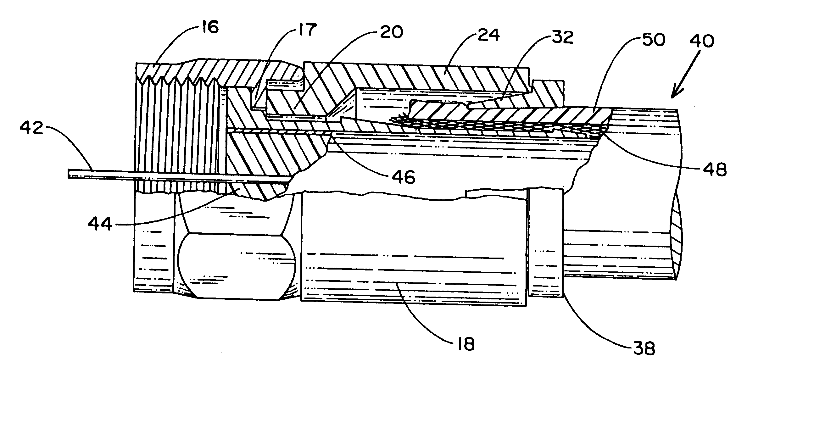
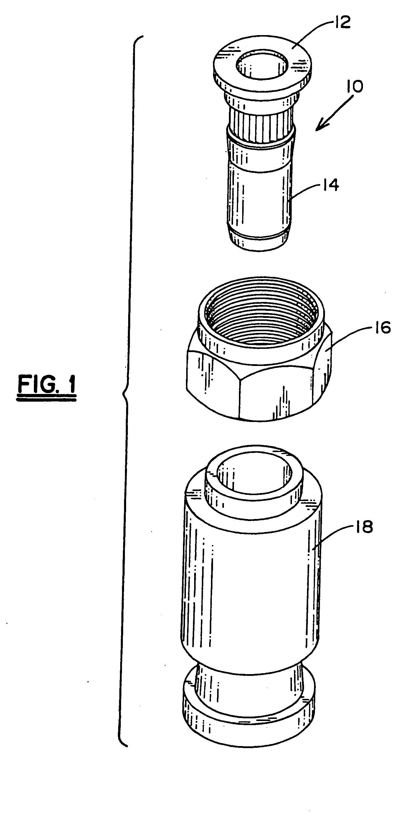
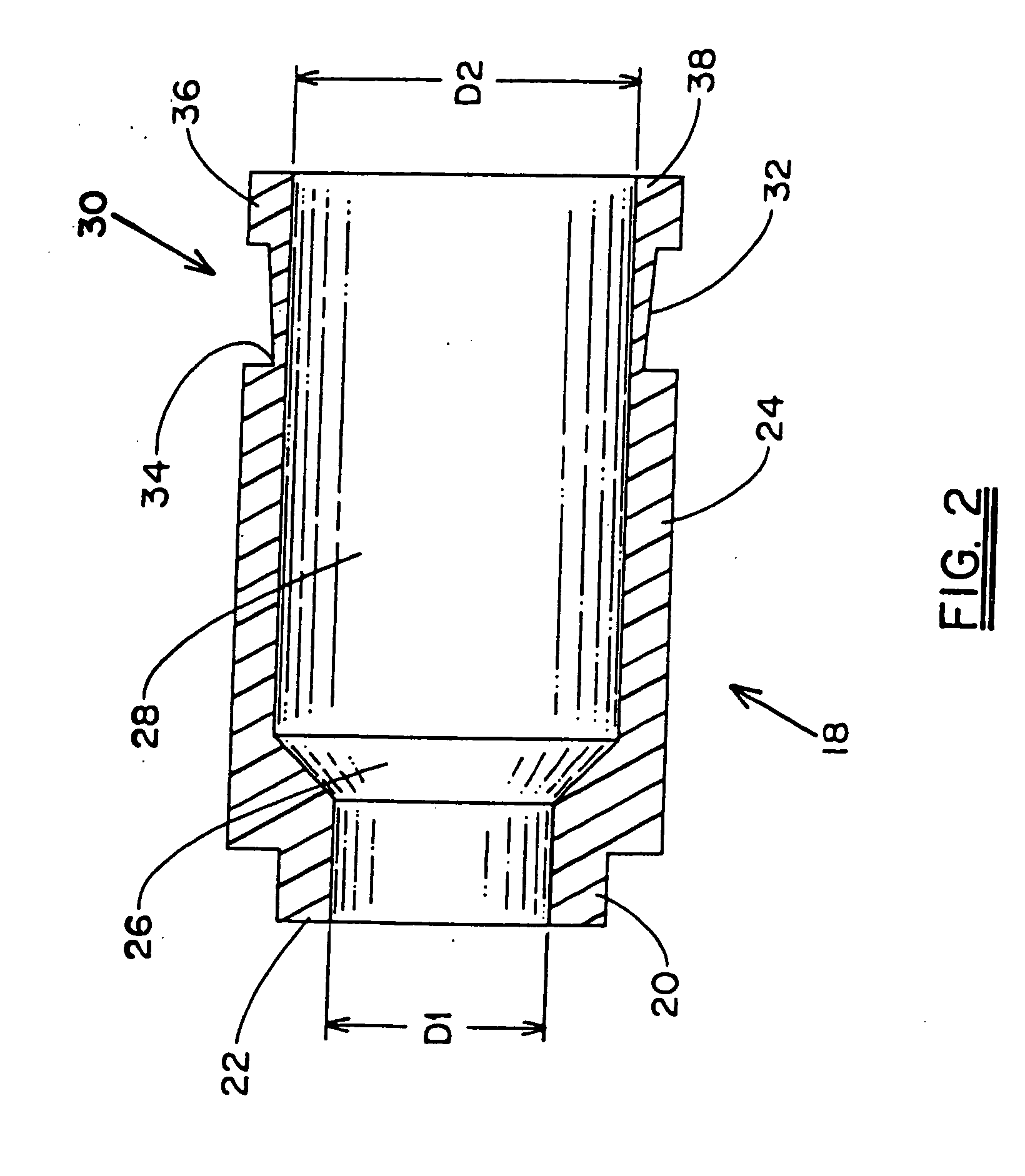
[0017] Referring now to the drawings, in FIG. 1 are shown the three components of the connector, namely, post 10, including integrally formed flange 12 and stem 14 sections, nut 16 and body 18. Post 10 and nut 16 are of conventional construction for use in this type of coaxial cable connector, body 18 being of unique construction, shown in a first embodiment in FIGS. 1-3. Body 18 is shown in cross section in FIG. 2 where it will be noted that the body includes three sections, integrally formed as a single piece. The first section 20 extends axially from one end 22 of body 18 for a portion of its axial length having inner diameter D1. Second section 24 includes tapered portion 26, connecting inner diameter D1 with larger inner diameter D2 of constant diameter portion 28 second section 24. Third section 30 extends integrally from second section 24 with the same inner diameter, but with a wall portion 32 of reduced thickness. The smallest thickness of wall portion 32 is at its juncture...

second embodiment

[0019] Turning now to FIGS. 4-6, the connector is shown with body, denoted by reference numeral 52, in combination with the conventional post and nut, here denoted by numerals 10′ and 16′, respectively. Body 52, as best seen in the sectional view of FIG. 5, again includes first section 54, extending from one end 56 of the body for the axial length thereof having inner diameter D1, second section 58, having tapered inner surface portion 60 connecting diameter D1 with larger inner diameter D2 of constant diameter portion 62 of second section 58. In this embodiment, third section 64 includes first, second and third wall portions 66, 68 and 70, respectively. First portion 66 extends from the junction of second and third sections 58 and 64, respectively, at a first area 72 of reduced thickness, tapering outwardly to its juncture with second portion 68 at a second area 74 of reduced thickness. Second portion 68 tapers outwardly to its junction with third portion 70 which extends to the ot...


PUM


Abstract

An F connector for mounting to the prepared end of a coaxial cable by compression of portions of the connector into tight frictional engagement with the cable. The body and compression ring of the usual F connector are incorporated in a unitary, one-piece body having three axial sections. The first section surrounds and frictionally engages the outer surface of the post stem in the usual manner. The second section is spaced from the stem to provide an annular space for the shielding and outer dielectric layers of the cable, also in the usual manner. A third section of the body is joined to the second section by an area of reduced thickness. In a first disclosed embodiment, the body fractures at the area of reduced thickness in response to an axial force applied to the third section in the direction of the second section. The wall thickness of the third section tapers outwardly from the area of reduced thickness, whereby movement of the third section between the inner surface of the second section and the outer surface of the cable by the axial force subsequent to fracture applies a radially compressive force to the cable and provides the desired tight frictional engagement of the connector and cable. In a second embodiment, the third section includes two, axially spaced areas of reduced thickness. The portions of the third section adjacent these reduced thickness areas are folded into the area between the second section and the cable as the axial force is applied, rather than being fractured.

Description

BACKGROUND OF THE INVENTION [0001] The present invention relates to connectors for installation on a terminal end of a coaxial cable as used, for example, in CATV applications by radial compression of the cable by a deformable body portion of the connector. More specifically, the invention relates to compression-type connectors wherein the number of parts is reduced and manner of effecting compression is different from conventional, prior art connectors of this type. [0002] A common type of connector installed on a terminal end of a coaxial cable includes elements known as a post, a nut, a body and a compression ring. The post includes a hollow stem integrally joined at one end to a flange. The nut is rotatably secured to the post, typically at or near the junction of the stem and flange, and the body surrounds the stem with a first portion, near the nut, in frictional engagement therewith and a second portion in outwardly spaced relation thereto. The compression ring, a hollow, sub...

Claims


Application Information

Patent Timeline
Patent Type & Authority Applications(United States)
IPC IPC(8): H01R9/05
CPCH01R9/0518
Inventor MONTENA, NOAHMALAK, STEPHEN
Owner PPC BROADBAND INC
Learn More