Splice plate for faceted radius grid

a technology of faceted radius and splice plate, which is applied in the direction of ceilings, walls, portal frames, etc., can solve problems such as inability to meet the needs of users

Active Publication Date: 2005-02-17
WORTHINGTON ARMSTRONG VENTURE
View PDF11 Cites 7 Cited by
  • Summary
  • Abstract
  • Description
  • Claims
  • Application Information

AI Technical Summary

Benefits of technology

[0014] The present invention is for an improved splice plate in the curved beam disclosed in the '850 application.

Problems solved by technology

This was not possible with the grid of the '850 application, since the cross beams were connected to the curved main beams away from the apexes, where the curved drywall did not contact the cross beams.

Method used


Image

  • Splice plate for faceted radius grid
  • Splice plate for faceted radius grid
  • Splice plate for faceted radius grid

Examples


Embodiment Construction

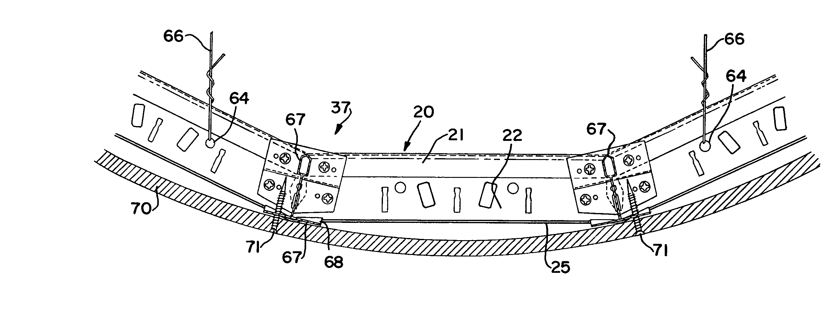
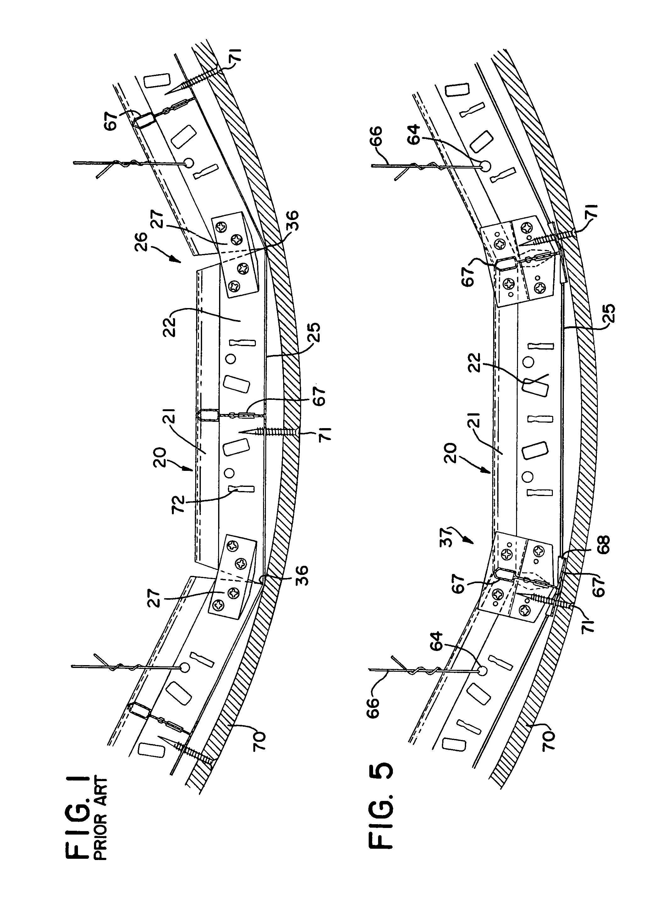
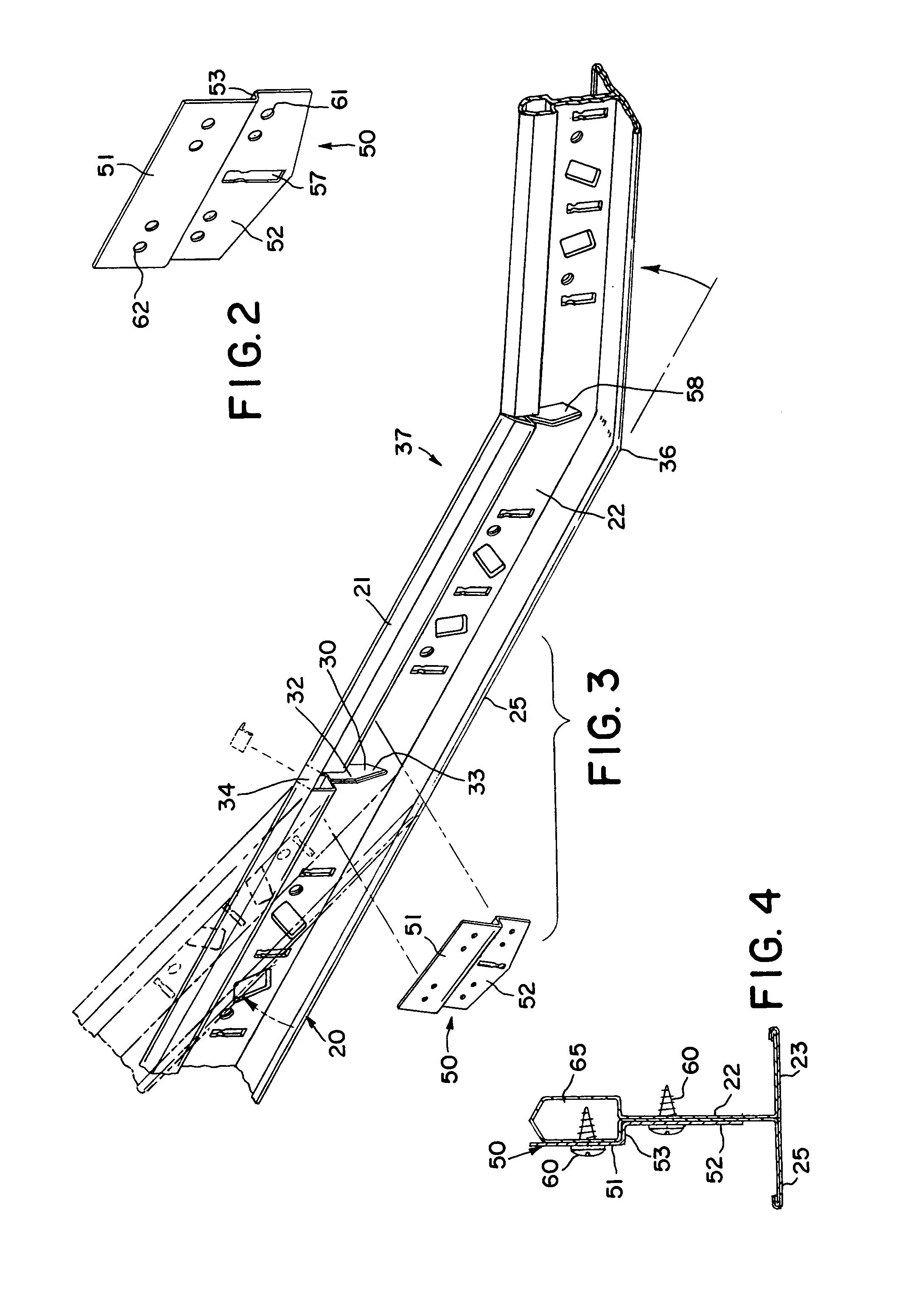
[0025] In making convex curved main beam 37, or a concave curved main beam 39, there is first formed a straight beam 20 of inverted T cross section having a bulb 21, web 22, and horizontal flanges 23 and 25, as disclosed in the '850 patent application. Roll forming of a straight beam 20 is well-known in the prior art.

[0026] As the straight, finished beam 20 continuously emerges from the roll forming operation, it is continuously cut into suitable lengths, for instance 12 feet, or 4 feet, or 2 feet, as with a flying shear. Connectors, well-known in the art, are formed on the ends of the straight beams 20. The beams 20 are then stacked and packaged for shipment to the job site for assembly into the grid of a suspended ceiling.

[0027] Cutouts 30, as seen in FIG. 3, are continuously formed in the straight beam 20 as the straight beam 20 is continuously being roll formed in the roll forming operation, as disclosed in the '850 application, before the continuous beam is cut into lengths. ...


PUM


Abstract

A splice plate for a faceted curved beam formed in the field from a straight beam. The splice plate can be used to fix the bends of either a convex or a concave curved beam used in the grid of a curved suspended drywall ceiling.

Description

BACKGROUND OF THE INVENTION [0001] 1. Field of the Invention [0002] The present invention relates to a curved suspended ceiling having a grid of inverted T beams suspended from a structural ceiling, with drywall boards fastened to the grid. [0003] 2. Description of the Prior Art [0004] Suspended ceilings in rooms are common. They have a grid of metallic beams that is suspended from an overhead structural ceiling, as by wires. [0005] The metallic beams used in the grids of suspended ceilings are made in a continuous process. A continuous strip of metal, usually steel, fed off a reel, is passed through a series of rolls that form the metal into an inverted T cross section having a web, a bulb at the top of the web, and horizontal flanges extending from the bottom of the web. Such beam construction is well-known. [0006] A straight, finished beam continuously emerges from the roll forming operation, and is cut, on the run, into suitable lengths, of, for instance, 12 feet, or 4 feet, or ...

Claims


Application Information

Patent Timeline
Patent Type & Authority Applications(United States)
IPC IPC(8): E04B9/06E04B9/10E04C3/40
CPCE04B9/061E04C3/40E04B9/10E04B9/068
Inventor AURIEMMA, JOSEPH
Owner WORTHINGTON ARMSTRONG VENTURE
Why Eureka
Try Eureka