Flashlight able to emit forceful light

a flashlight and light technology, applied in the field of flashlights able can solve the problems of inability to emit forceful light for use of tungsten filament lamps, inconvenience in storage and carrying of flashlights, and the inability to concentrate and focus on the thin lens of conventional flashlights, etc., and achieve the effect of easy production of high temperatur

Inactive Publication Date: 2005-02-17
WANG KUO TSAI
View PDF3 Cites 33 Cited by
  • Summary
  • Abstract
  • Description
  • Claims
  • Application Information

AI Technical Summary

Benefits of technology

[0016] Another embodiment of a flashlight able to emit forceful light in the present invention has two battery holders provided between the front and the rear cover. The two battery holders have the tension spring of their cathode conducting member lengthened and have six batteries received in the battery grooves, and then the two battery holders are fitted in a lengthened tube body. Thus, the six batteries have their electric force reinforced up to 9 volts, but the LED lamp is easy to produce high temperature and burn out in case more than 6 volts are supplied. Therefore, a resistance of ¼ watt has to be additionally provided to one pin of the press switch for modulating current and lowering voltage, enabling the flashlight to emit forceful and durable light.

Problems solved by technology

A conventional flashlight employs a tungsten filament lamp as a light emitter, as shown in FIG. 8, but the tungsten filament lamp cannot emit forceful light for use.
Generally, a conventional flashlight has its three batteries positioned linearly and conducted in series, not only lengthening the body of a flashlight but also resulting in inconvenience in storing and carrying of the flashlight.
Besides, the large arc-shaped reflector and the thin lens of a conventional flashlight can hardly concentrate and focus the light emitted by its LED lamp, always forming an astigmatic condition.

Method used


Image

  • Flashlight able to emit forceful light
  • Flashlight able to emit forceful light
  • Flashlight able to emit forceful light

Examples


Embodiment Construction

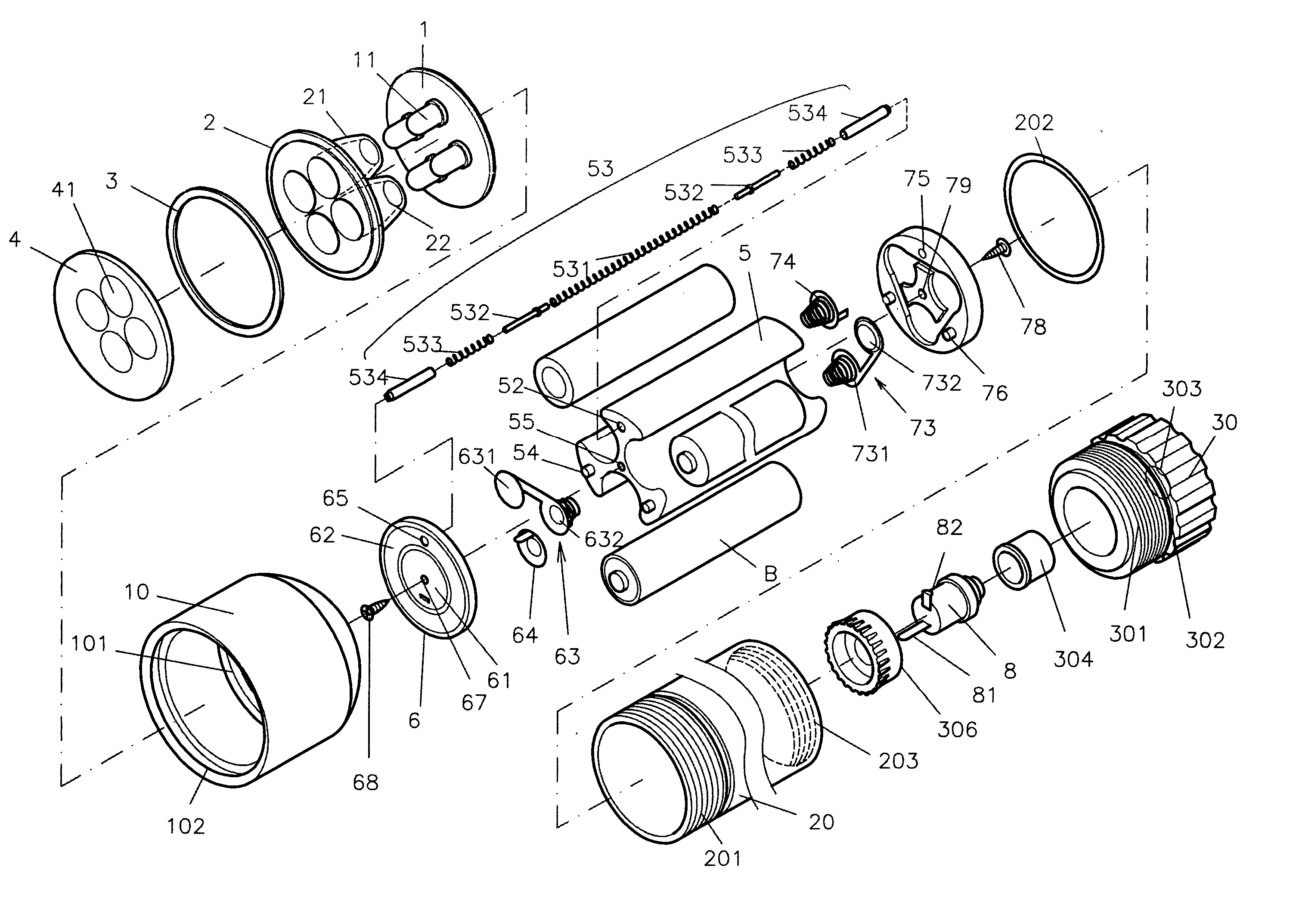
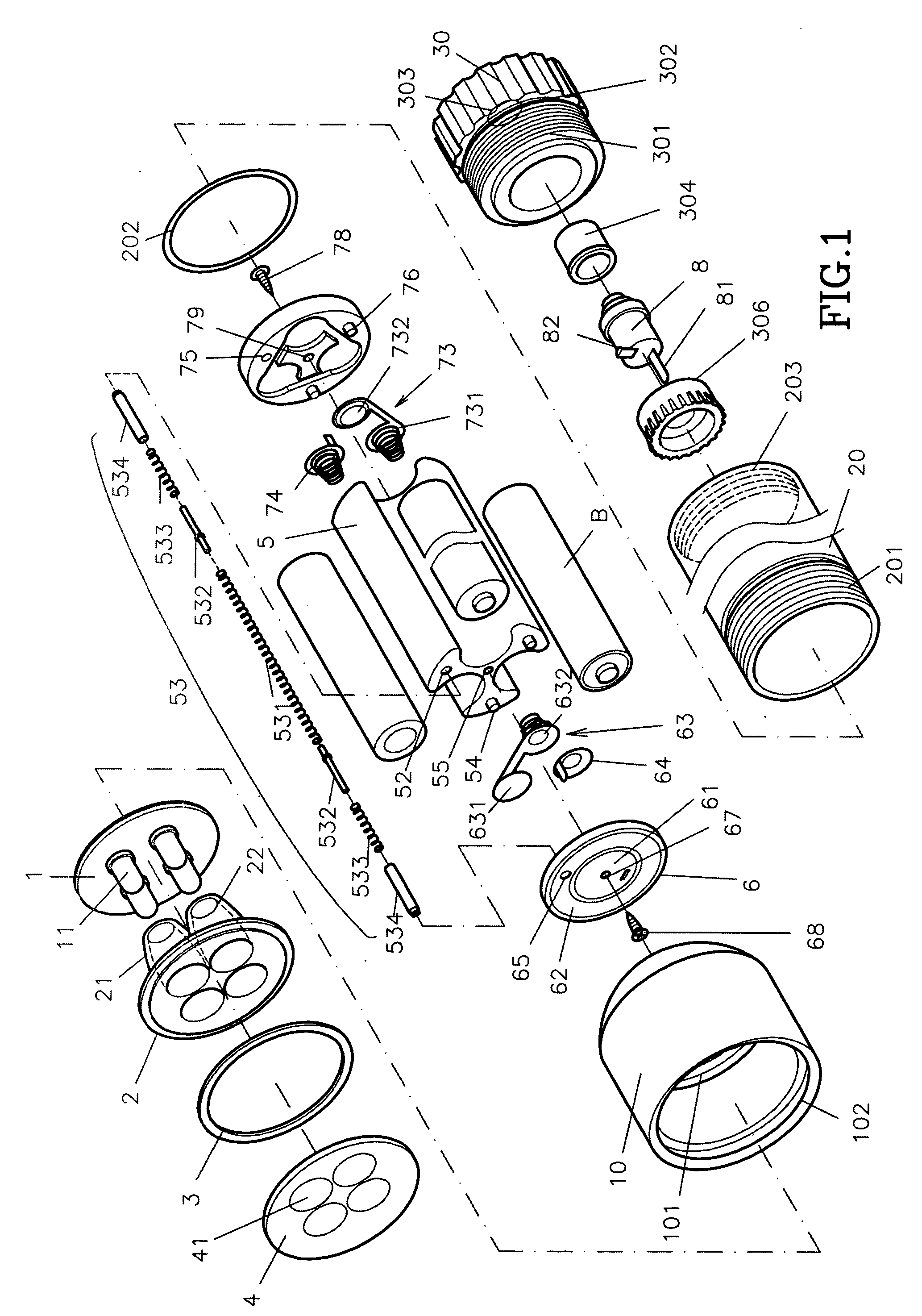
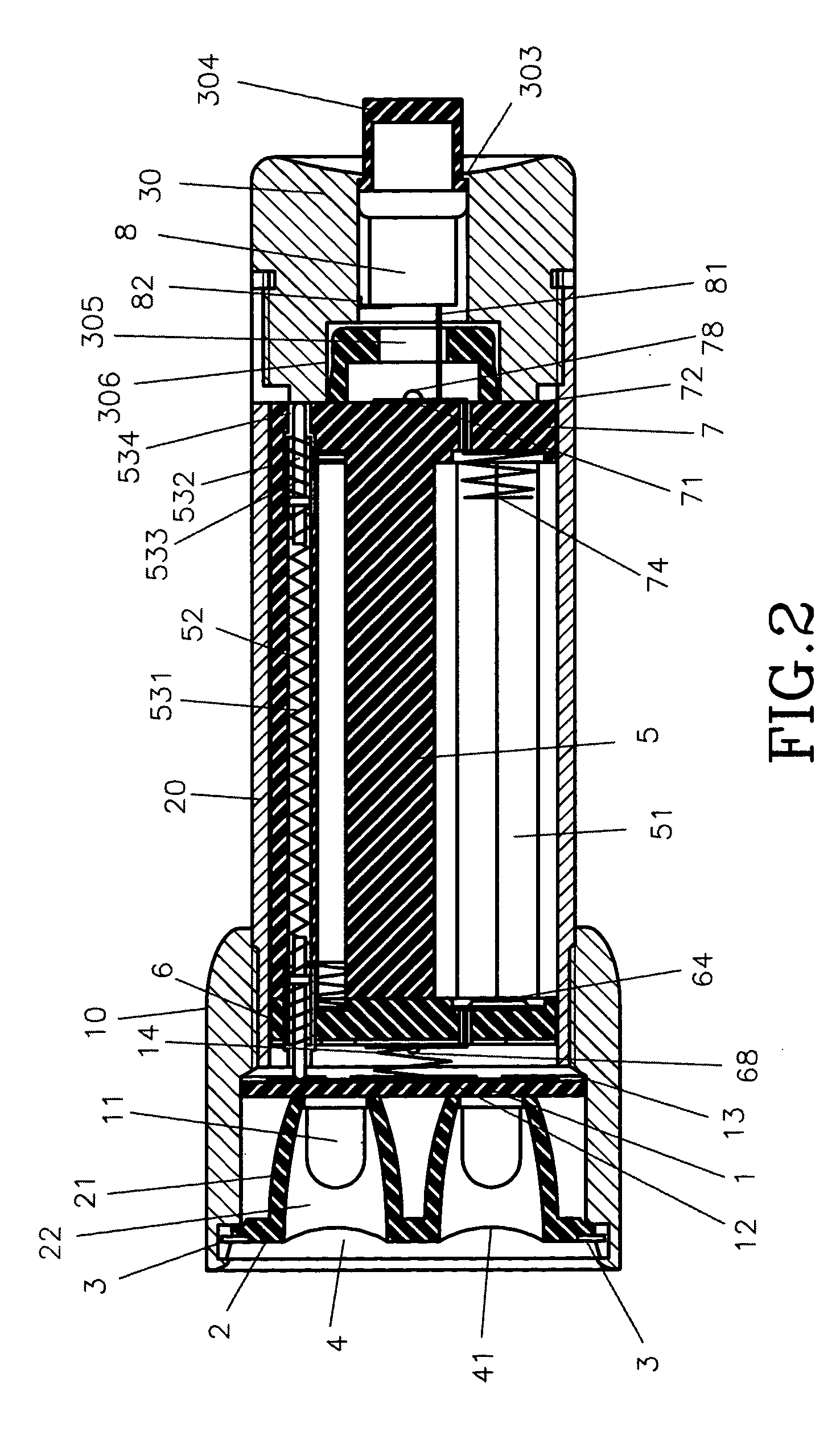
[0026] A first preferred embodiment of a flashlight able to emit forceful light in the present invention, as shown in FIGS. 1 and 2, includes a metallic lamp shade 10, a tube body 20, a bottom cover 30, a lamp base 1, a light-concentrating base 2, an O-shaped ring 3, a light-focusing lens 4, a battery holder 5, a front cover 6, a rear cover 7 and a press switch 8 combined together.

[0027] The lampshade 10 is formed with female threads 101 around the rear end to be screwed with the tube body 20, and a bent-in engage edge 102 at the front end. The lamp base 1, the light-concentrating base 2 and the O-shaped ring 3 are orderly fitted in the interior of the lampshade 10 and fixed in position by the light-focusing lens 4, which is forcefully pressed in the lampshade 10 through the engage edge 102.

[0028] The tube body 20 to receive therein the battery holder 5 and the front and the rear cover 6 and 7, having its front end formed with male threads 201 and fitted with an O-shaped ring 202 ...


PUM


Abstract

A flashlight able to emit forceful light includes a lamp base having plural LED lamps at the front side and an anode disc and a cathode ring on the rear side, a light-concentrating base having plural sleeves on the rear side for receiving the LED lamps, an O-shaped ring fitted on the light-concentrating base, a light-focusing lens fitted on the light-concentrating base, a battery holder having three battery grooves separated in parallel and having a cathode conducting member, a front cover having an anode disc and a cathode ring on the front side and a series conducting member and an anode conducting member on the rear side, a rear cover having a series conducting member and a cathode spring on the front side and a cathode disc and a cathode ring on the rear side, and a press switch fitted in a bottom base.

Description

BACKGROUND OF THE INVENTION [0001] 1. Field of the Invention [0002] This invention relates to a flashlight able to emit forceful light, particularly to one having the batteries separately positioned in parallel and conducted in series, able to shorten the length of a flashlight and focus the light of several LED lamps to enable the flashlight to emit powerful light. [0003] 2. Description of the Prior Art [0004] A conventional flashlight employs a tungsten filament lamp as a light emitter, as shown in FIG. 8, but the tungsten filament lamp cannot emit forceful light for use. For the present, LED lamps have taken the place of tungsten filament lamps in order to strengthen the light of a flashlight, but the electric source of the LED lamps is of high voltage and low current; therefore only when more than 4.5 volts are supplied can the LED lamp emit forceful light. A common battery contains only 1.5 volts so three batteries (4.5 volts) have to be provided for a flashlight to emit forcef...

Claims


Application Information

Patent Timeline
Patent Type & Authority Applications(United States)
IPC IPC(8): F21L2/00F21L4/02F21V23/04
CPCF21L4/027F21Y2101/02F21V23/0421F21V7/0083F21Y2115/10
Inventor WANG, KUO-TSAI
Owner WANG KUO TSAI
Why Eureka
Try Eureka