Transmission system

a transmission system and transmission system technology, applied in the field of transmission systems, can solve the problems of increasing costs and enlargement of the apparatus, and reducing so as to minimize the transmission of unnecessary signals

Active Publication Date: 2005-03-03
JVC KENWOOD CORP A CORP OF JAPAN
View PDF12 Cites 52 Cited by
  • Summary
  • Abstract
  • Description
  • Claims
  • Application Information

AI Technical Summary

Benefits of technology

[0013] An object of the present invention is to provide a transmission system capable of transmitting at least a digital HD video signal and a digital audio signal with single light and minimizing the transmission of unnecessary signals.
[0017] This aspect of the present invention eliminates the transmission of blanking signals with respect to vertical and horizontal synchronizing signals generated for a video signal. To at least secure synchronization between transmission and reception, this aspect transmits the first synchronizing data for vertical synchronization, the second synchronizing data serving as a delimiter signal for identifying and synchronizing each effective video line, pixel data for each effective line, sampled data of a digital audio signal to be transmitted within a field, and digital auxiliary data at least required for the video and audio signals. This aspect is capable of reducing a transmission capacity, optimizing an optical wireless transmission format, and relaxing a transmission speed.
[0019] Accordingly, this aspect of the present invention can optically transmit an uncompressed baseband digital HD video signal of 750 p or 1080 i component video (4:2:2) quality class at about 1.27 Gbps. In contrast, directly optically transmitting a 750 p component video signal containing blanking periods needs a transmission speed of about 1.49 Gbps. This transmission speed reduction achieved by this aspect of the present invention is quite meaningful when considering the present capacity of optical wireless transmission with single light, the application of optical wireless transmission to standard AV devices, and the sure transmission of signals for a distance of 10 m or over. In this way, this aspect of the present invention can secure a sufficient margin without enlarging the scale of electrical circuits for transmission and reception in optical wireless transmission carried out with single light.
[0024] This aspect fixes a transmittable video signal format to a maximum transmission capacity format. For a video signal of smaller transmission capacity than the maximum capacity, a shortage of video or audio signal is padded with null data. With this, any video signal, if using the same vertical synchronizing signal, is transmittable with the same transmission format without changing the transmission system, and the synchronized regeneration of video and audio signals is guaranteed.
[0026] This aspect calculates the master clock frequency used for transmission processing from an integer multiple of the sampling frequency of an audio signal and the greatest common devisor that satisfies the number of effective lines covered by a digital video signal. This aspect can simplify synchronizing and regenerating processes of the video and audio signals and reduce the sizes of circuits for synchronizing and regenerating the video and audio signals.

Problems solved by technology

The DVI standard mentioned above is limited to wired (cable) transmission and needs an audio cable in addition to a video cable when applied to AV devices.
Such a large FIFO and a fast transmission clock are unachievable.
This increases costs and enlarges the apparatus.
This also increases costs and enlarges the apparatus.
Although the blanking periods are used to transmit audio and control signals, entirely transmitting the blanking periods is wasteful.
Although these signal lines are gathered in a single cable, there is a necessity of conducting troublesome work of wiring them to a display section.

Method used


Image

  • Transmission system
  • Transmission system
  • Transmission system

Examples


first embodiment

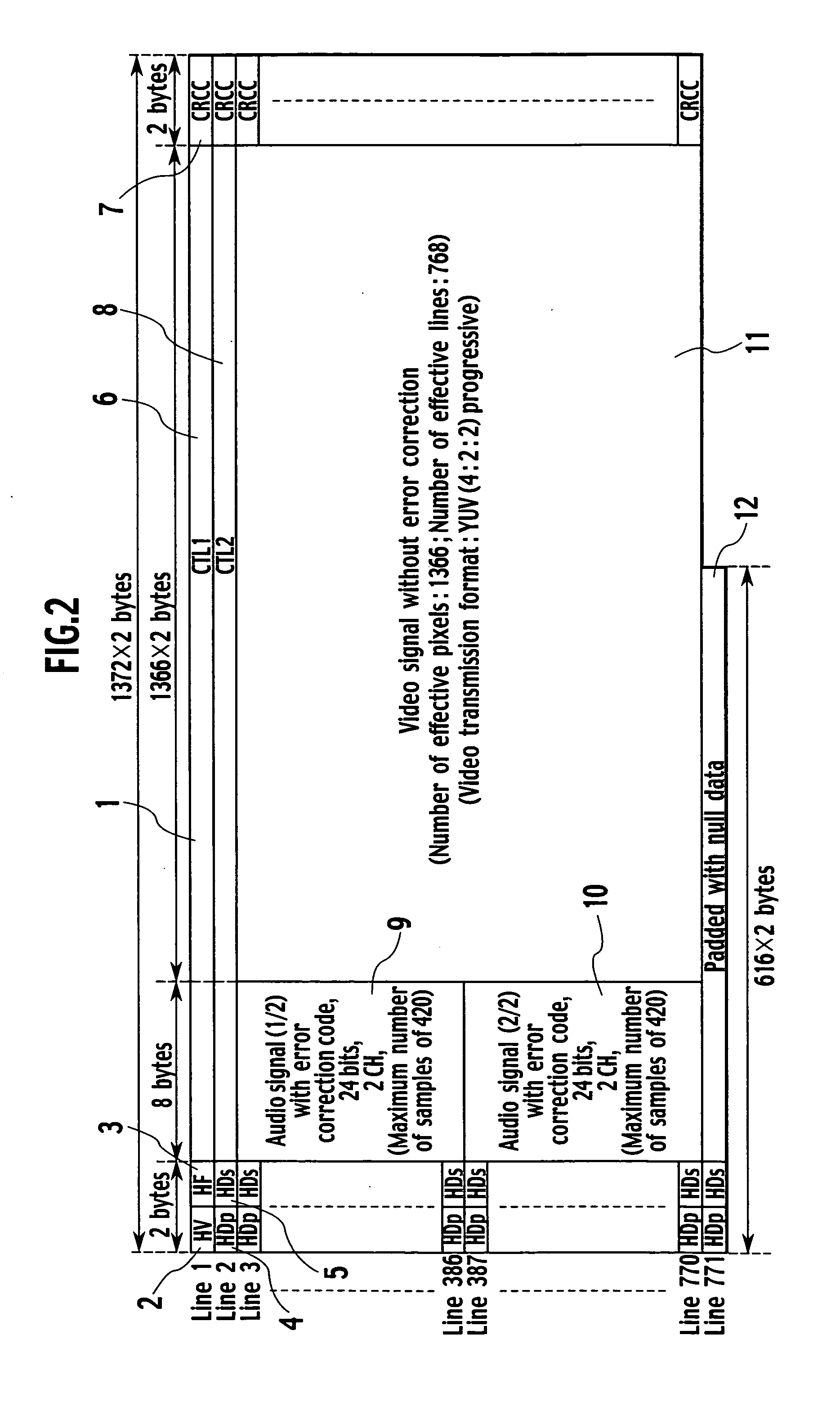
[0044] Accordingly, the present invention halves an audio signal to be transmitted within a field into the first half block 9 and second half block 10, to restrict the regeneration delay within two fields. To keep a balance between the audio signal and the video signal, a surplus area may be formed in the audio signal transmission blocks 9 and 10. Such a surplus area is padded with null data.

[0045] The last 771st line is to transmit redundant data to be caused when, for simplifying the synchronization and regeneration of video and audio signals, a master clock frequency for transmission processing is selected to be an integer multiple of the audio signal sampling frequency and the greatest common devisor satisfying the number of effective video signal lines. Accordingly, the 771st line is an invalid data area of “616×2” bytes including the synchronizing data (HDp) 4, the special data (HDs) 5, and the redundant data area padded with null data. The null data has no CRCC.

[0046] The au...

second embodiment

[0081] The second embodiment handles an interlace video signal. Namely, the signal format of FIG. 4 is used to transmit a 1080 i signal and an audio signal field by field. According to transmission image information, the special data (HF) 3 alternates an even field (HFe) and an odd field (HFo). Similar to the first line, the second line serially transmits auxiliary control data (CTL2) 8.

[0082] From the third line, an audio signal block (1 / 2) 9, an audio signal block (2 / 2) 10, and video signal data 11 are transmitted. Unlike the first embodiment, the video format of the second embodiment transmits 540 effective lines per field. Due to this, it is impossible for the second embodiment to continuously transmit the two audio signal blocks in an effective line direction (vertical direction) like the first embodiment. Accordingly, the format of the second embodiment transmits the two audio signal blocks in an effective pixel direction (horizontal direction).

[0083] Like the second line, th...


PUM


Abstract

A transmission system omits blanking signals from vertical and horizontal synchronizing signals for video data while securing synchronized transmission between a transmission side and a reception side. To achieve this, the transmission system transmits first synchronizing data (HV) for identifying vertical synchronization, second synchronizing data (HDp) for identifying and synchronizing an effective video line, pixel data for the effective video line, a required digital audio signal, and auxiliary control data. The transmission system can reduce a transmission capacity, optimize a transmission format for optical wireless transmission, and decrease a transmission speed.

Description

BACKGROUND OF THE INVENTION [0001] 1. Field of the Invention [0002] The present invention relates to a transmission system, and particularly, to a transmission system for an audio-video optical wireless transmission apparatus or a wired optical signal transmission apparatus, capable of multiplexing an uncompressed baseband digital HD (high definition) video signal, a digital audio signal, and a digital auxiliary control signal including a video signal format and an audio signal format, serially transmitting the multiplexed signal as an optical signal with an optical wireless transmitter or an optical signal transmission cable, receiving the optical signal, demultiplexing the received signal into the video signal, audio signal, and auxiliary control signal, and regenerating the video and audio signals. [0003] 2. Description of Related Art [0004] There are known transmission systems that convert an uncompressed baseband digital HD (high definition) video signal into an optical signal ...

Claims


Application Information

Patent Timeline
Patent Type & Authority Applications(United States)
IPC IPC(8): H04J3/04H04N5/268H04N7/22H04N7/24
CPCG09G5/006H04N5/268
Inventor SATOH, YASUOYUGAMI, MASAFUMI
Owner JVC KENWOOD CORP A CORP OF JAPAN
Why Eureka
Try Eureka