Multi-function end effector

a technology of end effectors and end effects, applied in the field of end effectors, can solve the problems of limited power, drive motors with multiple functions, and inconvenient use,

Active Publication Date: 2005-03-03
THE BOEING CO
View PDF9 Cites 53 Cited by
  • Summary
  • Abstract
  • Description
  • Claims
  • Application Information

AI Technical Summary

Problems solved by technology

A drawback of this type of end effector is that a plurality of drive motors are required.
In order to keep the overall size and weight of the end effector reasonably low, the drive motors must be relatively small and hence are limited in power.
In some applications, it may be difficult or impossible to access both sides of a workpiece.

Method used


Image

  • Multi-function end effector
  • Multi-function end effector
  • Multi-function end effector

Examples


Embodiment Construction

[0034] The present invention now will be described more fully hereinafter with reference to the accompanying drawings, in which preferred embodiments of the invention are shown. This invention may, however, be embodied in many different forms and should not be construed as limited to the embodiments set forth herein; rather, these embodiments are provided so that this disclosure will be thorough and complete, and will fully convey the scope of the invention to those skilled in the art. Like numbers refer to like elements throughout.

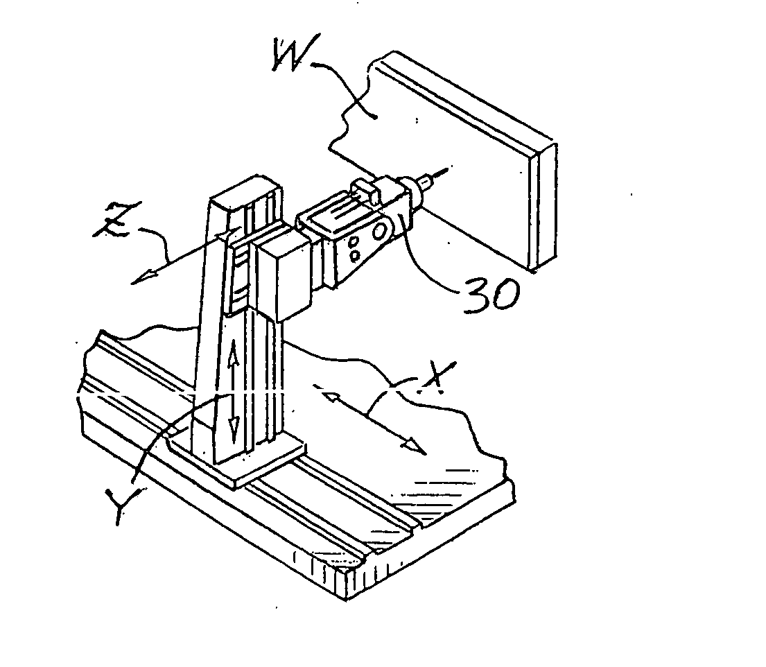
[0035] With reference to the drawings, an end effector 30 in accordance with one embodiment of the invention is depicted in various views and performing various operations on a workpiece. The end effector 30 is capable of being used in conjunction with a motion platform such as a multi-axis machine or robot as shown in FIG. 1, which positions the end effector 30 relative to the workpiece W being worked upon.

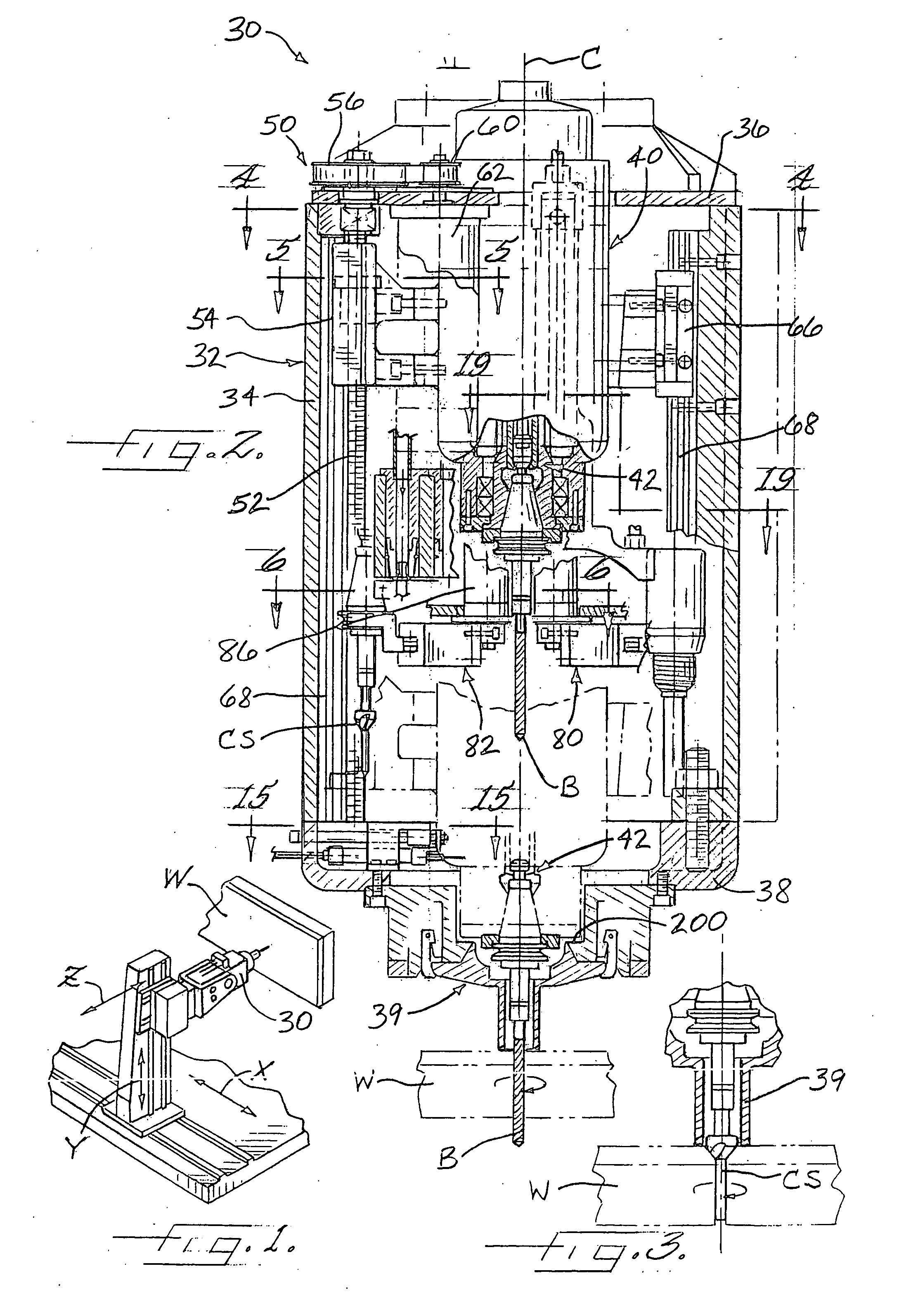
[0036]FIG. 2 shows the end effector 30 section...


PUM

PropertyMeasurementUnit
translational movementaaaaaaaaaa
sizeaaaaaaaaaa
weightaaaaaaaaaa

Abstract

A multi-function end effector includes a plurality of tool change mechanisms in a housing in which a spindle is also mounted for translation along an axis of the spindle. Each tool change mechanism has a gripper that releasably grips a tool holder in which a tool is mounted. The gripper of each tool change mechanism is movable between a stowed position to a tool-change position in which the gripper is coaxially aligned with the axis of the spindle for placing a tool holder held in the gripper in a position to be received by the spindle and for positioning the gripper to receive a tool holder from the spindle. The tools mounted in the tool holders include a drill bit, a countersink tool, and a fastener insertion tool. The end effector also includes a fastener feed system, a hammer device, and a sealant applicator.

Description

FIELD OF THE INVENTION [0001] The present invention relates to end effectors for mounting on the working end of a motion platform such as a robotic arm. The invention relates more particularly to end effectors having the capability to automatically change tools carried with the end effector so as to be able to perform a plurality of different work operations on a workpiece, and to end effectors operable to install blind or one-sided installation (OSI) fasteners such as blind rivets or the like. BACKGROUND OF THE INVENTION [0002] Various types of multi-function end effectors having a tool changing ability are known. One type of multi-function end effector has a number of tool modules each having a tool holding device coupled with a drive motor. The modules can be interchanged on a feeding block, which in turn can advance and retract a tool module for performing work operations. A drawback of this type of end effector is that a plurality of drive motors are required. In order to keep ...

Claims


Application Information

Patent Timeline
Patent Type & Authority Applications(United States)
IPC IPC(8): B21J15/14B23Q3/155B23Q3/157
CPCB21J15/14B23Q3/15513B23Q3/15713Y10S483/90Y10T483/1795Y10T483/1774Y10T29/5118Y10T483/115Y10T483/1752B21J15/142
Inventor EVERSON, CURTISJONES, EVERETT E.JONES, MICAHEL K.RULE, SCOTT LEEMATTEEKA, MAHER A.FABRIS, ARNOLD J.BRUNNER, WILLIAM M. JR.GRANOT, BENNYEINAV, OMER
Owner THE BOEING CO
Why Eureka
Try Eureka