
Shaft lock mechanism for a rotary power hand tool

a technology of shaft lock and hand tool, which is applied in the direction of portable power-driven tools, manufacturing tools, drilling machines, etc., can solve the problems of tool damage and ragged construction, and achieve the effect of convenient assembly and retention

Inactive Publication Date: 2005-03-10
CREDO TECH CORP
View PDF13 Cites 1 Cited by
  • Summary
  • Abstract
  • Description
  • Claims
  • Application Information

AI Technical Summary

Benefits of technology

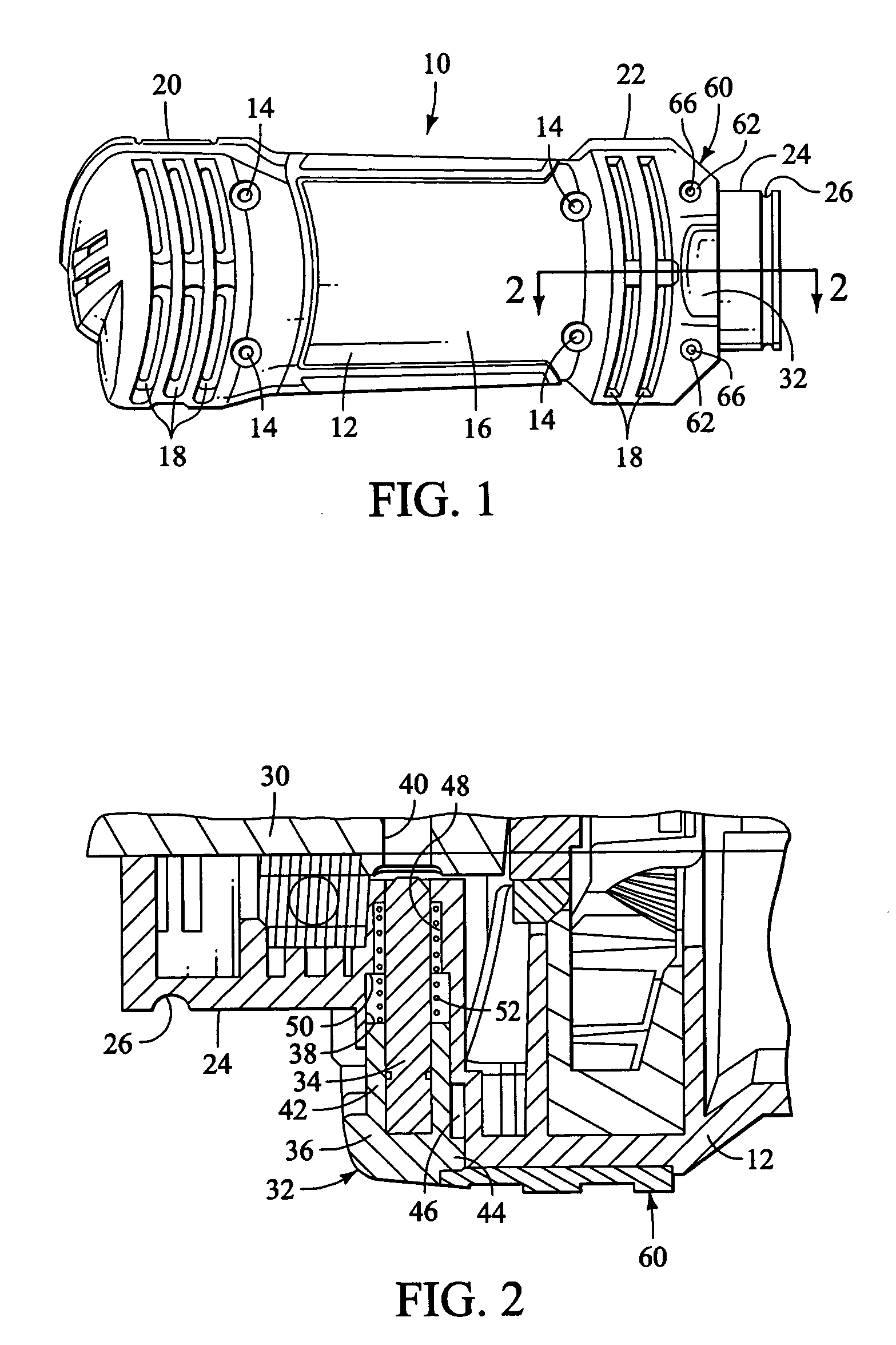
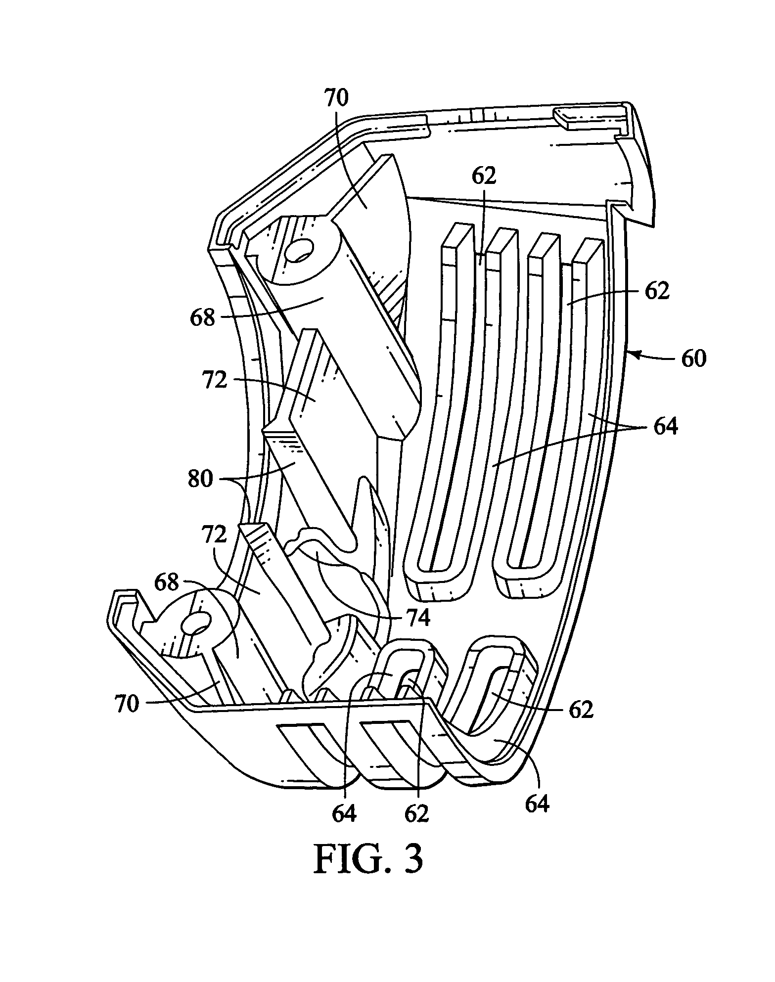
[0006] A preferred embodiment comprises a power hand tool of the type which has a generally cylindrical elongated plastic housing with a motor contained within the housing and having an output shaft that extends from the front end portion of the hand tool, and which has a metal front end portion that cooperates with the plastic housing to strengthen a shaft locking mechanism located at the front end of the hand tool. The metal front end portion not only strengthens the outer surface of the housing in the front end portion of the tool, but also has a pair of internal structural ribs positioned to absorb stress that may be present in the housing as a result of force applied to the shaft locking mechanism. The preferred embodiment is also designed to enable the shaft locking pin mechanism to be easily assembled and retained without the need for an E-clip or C-clip as is commonly the practice in commercially available spiral saw hand tools.

Problems solved by technology

Because these tools are often the subject of abusive treatment, they must be ruggedly built to last.
Using the locking pin mechanism as a brake is not what the tool is designed for and can result in damage to the tool.

Method used


Image

  • Shaft lock mechanism for a rotary power hand tool
  • Shaft lock mechanism for a rotary power hand tool
  • Shaft lock mechanism for a rotary power hand tool

Examples


Embodiment Construction

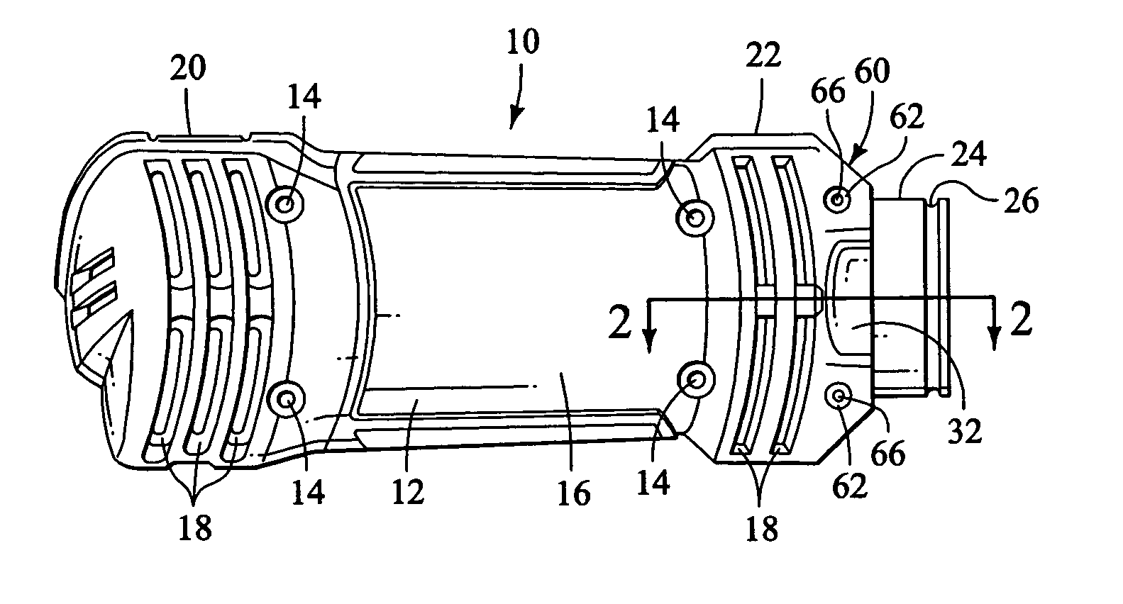
[0015] A preferred embodiment of the rotary power hand tool of the present invention is indicated generally at 10 in FIG. 1. It has a housing that is preferably comprised of an upper section 12 which is visible in FIG. 1 and a lower section that is not. The two sections are designed to mate with one another and are held together by four screws or star configured bolts 14 that engage a surface in the lower section. Both of the mating plastic sections and preferably made of a plastic or plastic like material which is relatively light weight but strong and impact resistant.

[0016] A motor (not shown) is located in a central portion 16 of the hand tool and ventilation openings 18 are located in a rear portion 20 as well as a front portion 22. A nose portion 24 is preferably located at the front end portion 22, which has a generally cylindrical shape and an annular recess 26 at the outer end thereof. The nose portion 24 is provided so that accessories or attachments can be mounted to the...


PUM

PropertyMeasurementUnit
cylindrically shapeaaaaaaaaaa
diameteraaaaaaaaaa
rotational torqueaaaaaaaaaa

Abstract

A preferred embodiment comprises a power hand tool of the type which has a generally cylindrical elongated plastic housing with a motor contained within the housing and having an output shaft that extends from the front end portion of the hand tool, and which has a metal front end portion that cooperates with the plastic housing to strengthen a shaft locking mechanism located at the front end of the hand tool. The metal front end portion not only strengthens the outer surface of the housing in the front end portion of the tool, but also has a pair of internal structural ribs positioned to absorb stress that may be present in the housing as a result of force applied to the shaft locking mechanism. The preferred embodiment is also designed to enable the shaft locking pin mechanism to be easily assembled and retained without the need for an E-clip or C-clip as is commonly the practice in commercially available spiral saw hand tools.

Description

BACKGROUND OF THE INVENTION [0001] The present invention generally relates to power rotary hand tools and more particularly to an improved shaft lock mechanism for the same. [0002] Small rotary hand tools that have a generally cylindrical housing or case have been marketed for many years for use in carrying out various woodworking and metal working tasks by hobbyists as well as commercial artisans. Such rotary hand tools generally have a motor unit with a rotary output shaft extending from the nose end and often have a nose portion that is configured to connect to various accessories or attachments. Some of these rotary hand tools are somewhat larger and more powerful and are known in the building trade as spiral saws that use a side cutting bit to penetrate and to rapidly cut holes for electrical outlets, light fixtures and switches and the like in dry wall. Because these tools are quite powerful even though they are relatively small, they are convenient to use on a jobsite or just...

Claims


Application Information

Patent Timeline
Patent Type & Authority Applications(United States)
IPC IPC(8): B24B23/02B25F5/00B27B5/38
CPCB24B23/022B25F5/001Y10T409/30392Y10T409/306608B27B5/38
Inventor RILEY, JONATHAN G.POZGAY, DAVID
Owner CREDO TECH CORP
Learn More