Push button bayonet tube connector

Inactive Publication Date: 2005-03-17
VALUE PLASTICS
View PDF11 Cites 131 Cited by
  • Summary
  • Abstract
  • Description
  • Claims
  • Application Information

AI Technical Summary

Benefits of technology

[0006] The present invention was developed to allow a user to more easily connect and disconnect the ends of a tubular structure, even when the tubular structure has a small diameter. The present invention provides a reversible connection that

Problems solved by technology

As tubing diameters reduce in size, bayonet structures need to also reduce in s

Method used


Image

  • Push button bayonet tube connector
  • Push button bayonet tube connector
  • Push button bayonet tube connector

Examples


Embodiment Construction

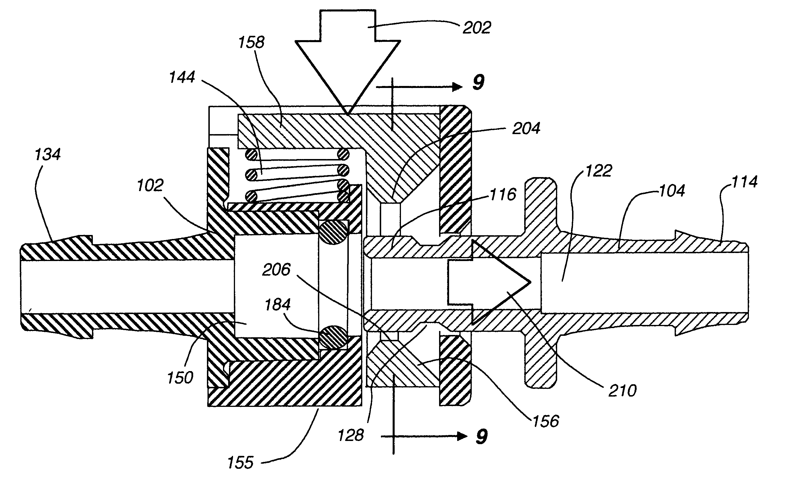
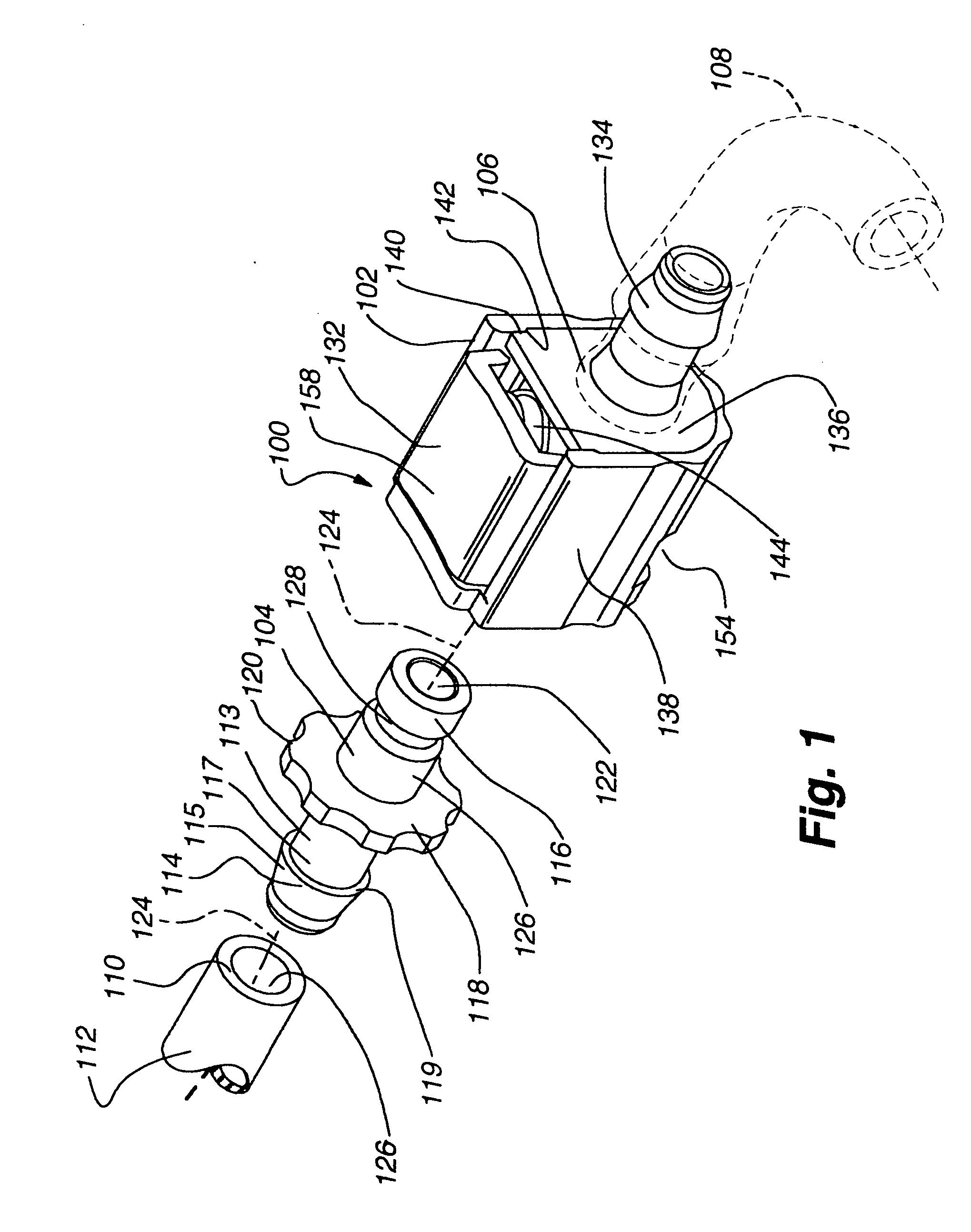
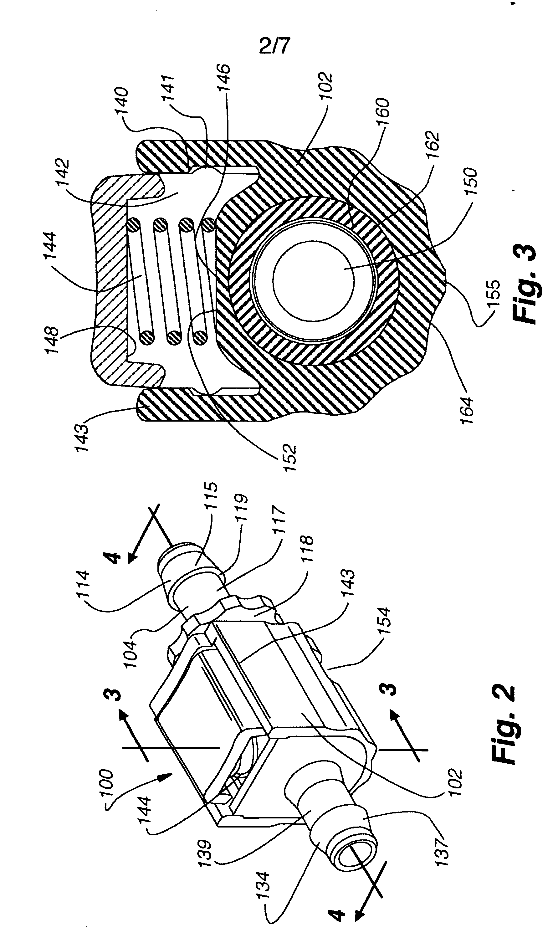
[0021] A push button bayonet assembly for connecting two fluid passageways is provided. The push button bayonet assembly reversibly couples two fluid passageways to each other, one fluid passageway connected to a male member of the assembly and one fluid passageway connected to a female member of the assembly. The male and female members are secured together via physical interference held in position by a spring biased assembly (or other similar biasing force), the force being released by actuation of a push button on the female housing engagement assembly. Operation of the selective connection between the male and female members is fast and convenient. The assembly disclosed in the present invention is used to connect any two fluid passageways together, including passageways that contain pressurized gases or fluids, and is especially adaptable for small scale designs. This invention can be used on tubes having inner diameters of one-sixteenth of an inch or less to tubes having an i...


PUM


Abstract

A push button bayonet tube connector assembly for releasably connecting two fluid passageways is described. The bayonet assembly includes a male and female member. The female member includes a spring actuated push button engagement assembly having a locked or engaged position and an unlocked or disengaged position with the male member. A method for fabricating the push button bayonet tube connector assembly is also described.

Description

CROSS REFERENCE TO RELATED APPLICATIONS [0001] This application claims priority to U.S. Provisional Patent Application No. 60 / 502,500 titled “Push Button Bayonet Tube Connector,” filed Sep. 12, 2003, which is hereby incorporated by reference herein.FIELD OF INVENTION [0002] The invention generally relates to tube connectors, and more particularly to tube connectors having push button release mechanism for releasably connecting two or more sections of tubing. BACKGROUND OF INVENTION [0003] Tube connectors have a variety of applications in, for example, the biomedical, pharmaceutical, and light industrial industries. Tube connectors generally are required where some level of control is required over the flow of a fluid within a fluid passageway. Generally, such control is exerted over the fluid by incorporating a tube connector within the path of the tubing. [0004] There are a variety of tube connectors available on the market. One such tube connector is the bayonet connector, which g...

Claims


Application Information

Patent Timeline
IPC IPC(8): F16L37/084
CPCF16L37/0841
Inventor WICKS, JEFFREY CLARK
Owner VALUE PLASTICS
Why Eureka
Try Eureka