
Automobile wheel lighting system

Active Publication Date: 2007-05-22
THE MCINNIS CO LLC
View PDF14 Cites 3 Cited by
  • Summary
  • Abstract
  • Description
  • Claims
  • Application Information

AI Technical Summary

Benefits of technology

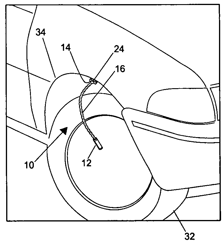
[0011]It is another object of the invention to provide a wheel lighting system that allows a user to easily connect and disconnect the lighting assemblies. Accordingly, a fixed connector is mounted to the automobile adjacent each wheel and is electrically connected to the automobile electrical system. The lighting assembly has a mating connector that facilitates easy connection and disconnection with the fixed connector.
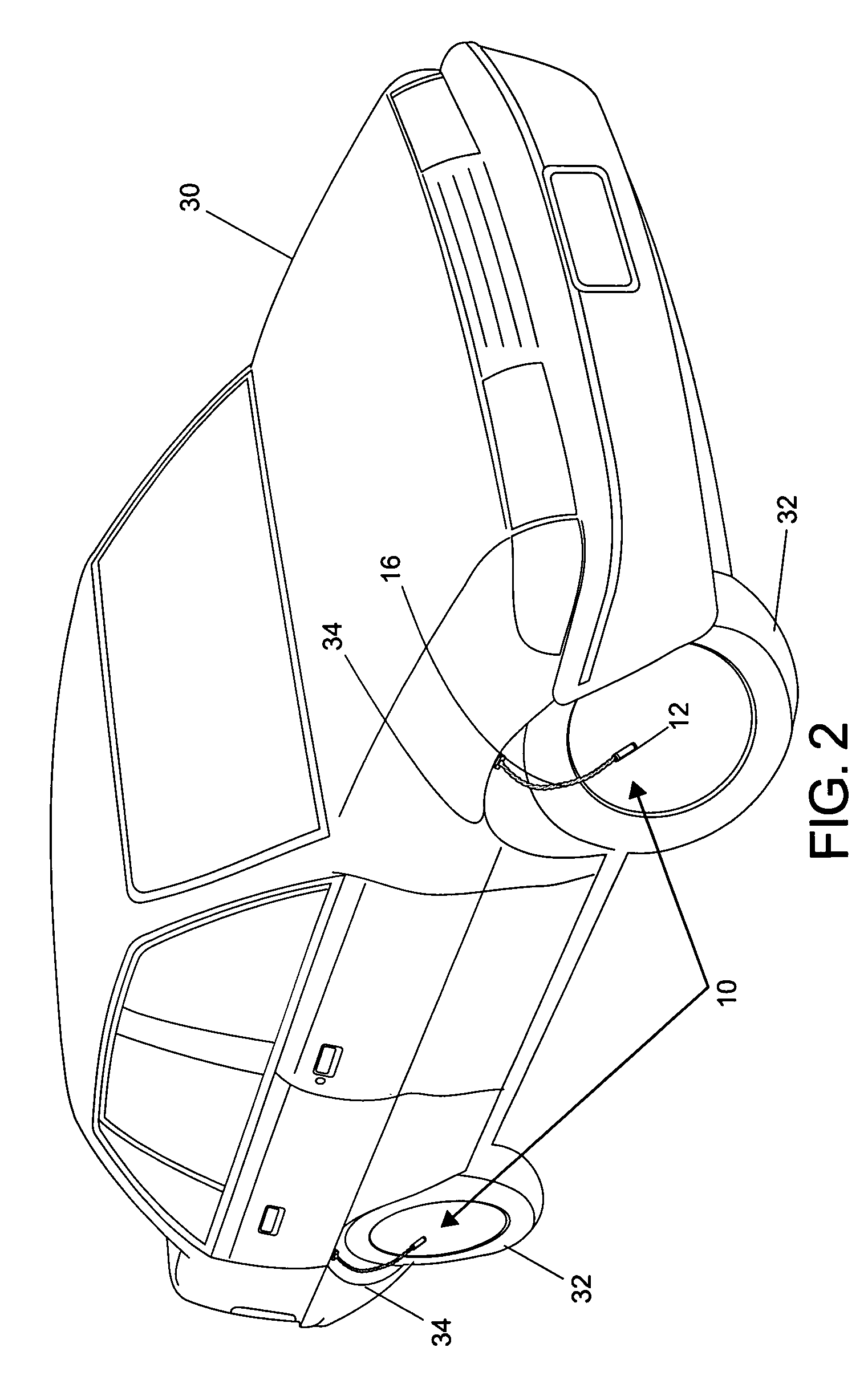
[0012]It is a further object of the invention to provide a lighting system that allows one of the lighting assemblies to be connected adjacent one of the tires, when needed, for changing that tire or effecting emergency repairs. Accordingly, the present invention provides fixed connectors within the wheel wells, so that the light assembly can be attached thereat by simply securing the mating connector within the fixed connector and thereby illuminating the wheel and region immediately therearound.

Problems solved by technology

Few conventional lights, however, are intended to illuminate exterior surfaces of the automobile.
At night, however, the flash and appeal of the custom rims is largely lost as the automobile rims rotate silently in the dark.
In addition, the lack of illumination can be hazardous when emergency repairs are necessary.
In particular, a flat tire on a dark road can be nearly impossible to fix.
Without another person standing-by holding a flashlight, the act of changing a tire can involve significant fumbling in the dark, and can even be dangerous.

Method used


Image

  • Automobile wheel lighting system
  • Automobile wheel lighting system
  • Automobile wheel lighting system

Examples


Embodiment Construction

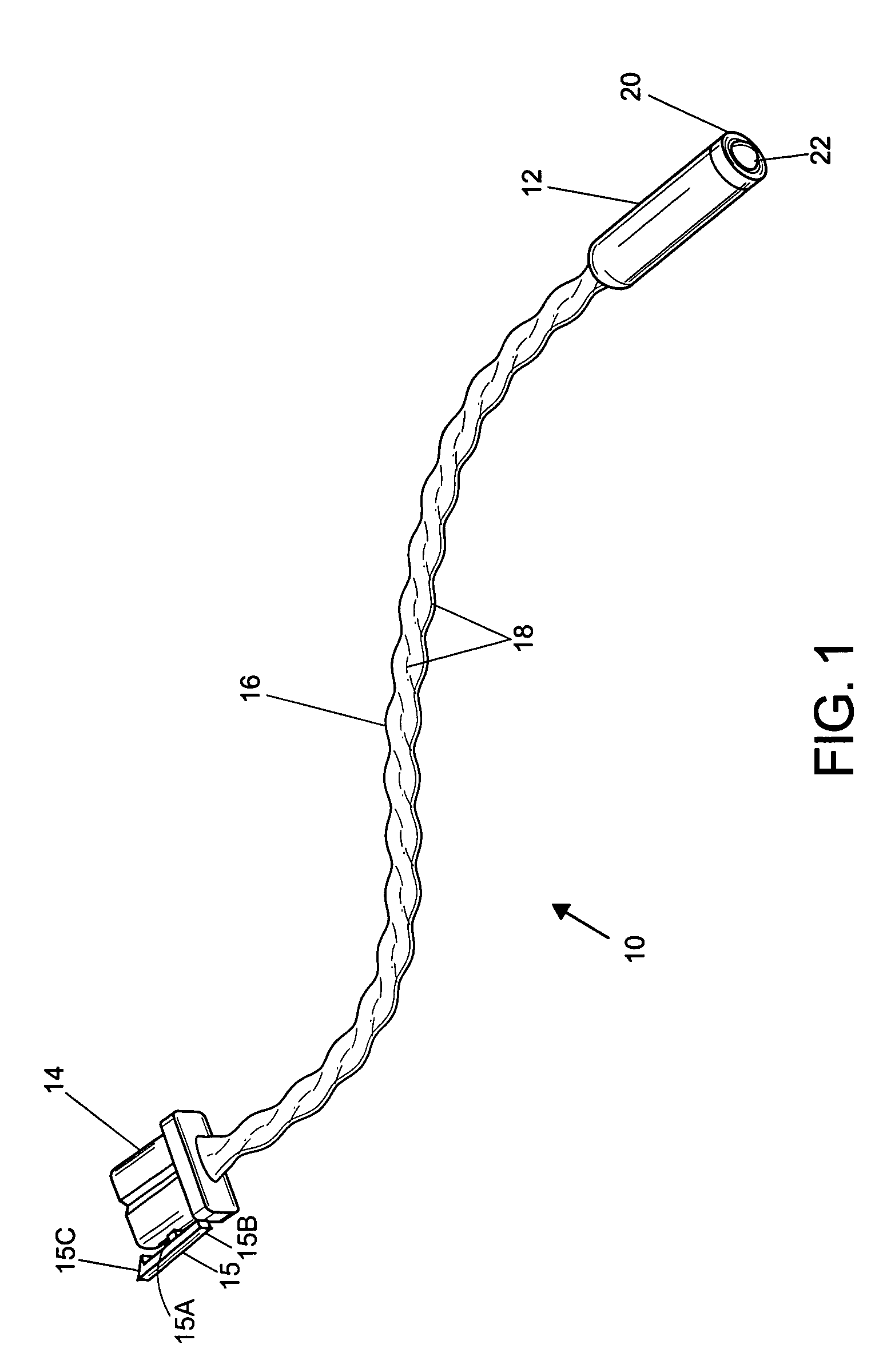
[0022]FIG. 1 illustrates a lighting assembly 10 according to the present invention. The lighting assembly includes a lighting head 12, a mating connector 14, and a flexible cord 16 extending between the lighting head 12 and mating connector 14. The flexible cord 16 includes a pair of wires 18 that are preferably twisted tightly together for strength and flexibility. The pair of wires 18 electrically connect the lighting head 12 and connector 14.

[0023]The lighting head 12 includes a reflector assembly 20, and an LED 22. It should be noted that the LED 22 may be recessed within the reflector assembly 20. The LED is in fact electrically connected to the mating connector 14 with the wires 18. In addition, a current limiting resistor is preferably provided within the lighting head 12 to prevent damage to the LED when it is connected a standard twelve volt supply. The reflector assembly 20 is preferably constructed to direct light from the LED 22 in a fairly narrow pattern so that it prov...


PUM


Abstract

An automobile wheel lighting system, for use in an automobile having a battery, wheels, and a wheel well associated with each wheel. A fixed connector is mounted within each wheel well and is electrically connected to the battery. At least one lighting assembly is used to selectively illuminate one of the wheels. Each lighting assembly includes a mating connector, a lighting head having an LED and a reflector assembly, and a flexible cord extending between the mating connector and lighting head. The mating connector is secured within the fixed connector in the wheel well adjacent to the wheel to be illuminated, and the cord extended outwardly from the automobile and flexed to direct the lighting head toward the wheel.

Description

BACKGROUND OF THE INVENTION[0001]The invention relates to an automobile wheel lighting system. More particularly, the invention relates to a light assembly that selectively attaches adjacent one of the wheels to illuminate that wheel.[0002]Conventional automotive lights do not illuminate the outside of the automobile. Interior lights illuminate dashboard gauges, controls, and displays. Headlights project outwardly to light the road ahead. A vehicle's taillights warn other vehicles of the presence of the vehicle. Turn lights signal other vehicles of the intention of the driver. Few conventional lights, however, are intended to illuminate exterior surfaces of the automobile. With the exception of license plate lights then, the exterior of the automobile remain substantially un-lit.[0003]Many automobile owners customize the appearance of their vehicle by selecting custom design wheels or rims to replace the “stock” wheels provided by the manufacturer. At night, however, the flash and a...

Claims


Application Information

Patent Timeline
IPC IPC(8): B60Q1/00B60Q1/26
CPCB60Q1/2657B60Q1/326
Inventor LOWMAN, JASONWILLIAMS, RANDALMONGEON, SCOTT
Owner THE MCINNIS CO LLC
Learn More