Brake device having adjustable spring member

a technology of spring member and brake device, which is applied in the direction of cycle brakes, cycle equipment, etc., can solve the problems of rods not being adjusted, rods may also have a good chance of being disengaged from the brake arms, and good chance of disengagemen

Inactive Publication Date: 2005-03-24
TSAI SHIH FAN
View PDF13 Cites 36 Cited by
  • Summary
  • Abstract
  • Description
  • Claims
  • Application Information

AI Technical Summary

Problems solved by technology

However, the other ends of the longitudinal spring rods have a good chance to be disengaged from the brake arms in use.
However, the other ends of the longitudinal spring rods may also have a good chance to be disengaged from the brake arms in use.
In addition, the longitudinal spring rods may not be adjusted to different spring biasing force to apply or act onto the brake arms, such that the longitudinal spring rods may not be adjusted to different spring biasing force to actuate the brake arms.

Method used


Image

  • Brake device having adjustable spring member
  • Brake device having adjustable spring member
  • Brake device having adjustable spring member

Examples


Embodiment Construction

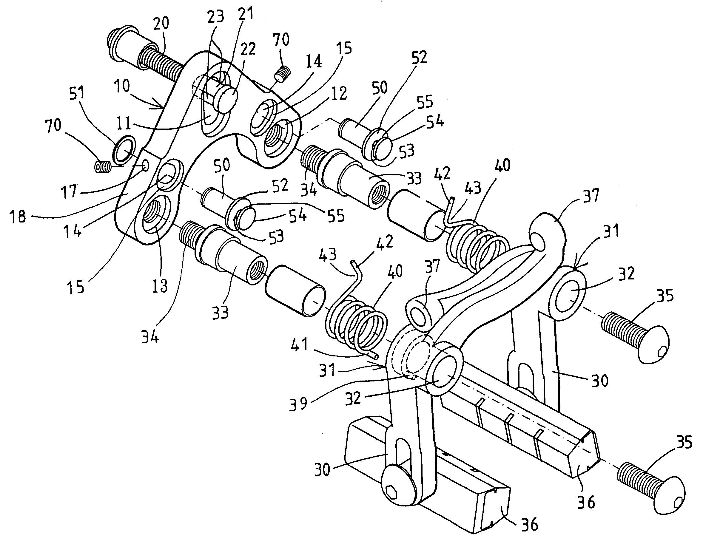
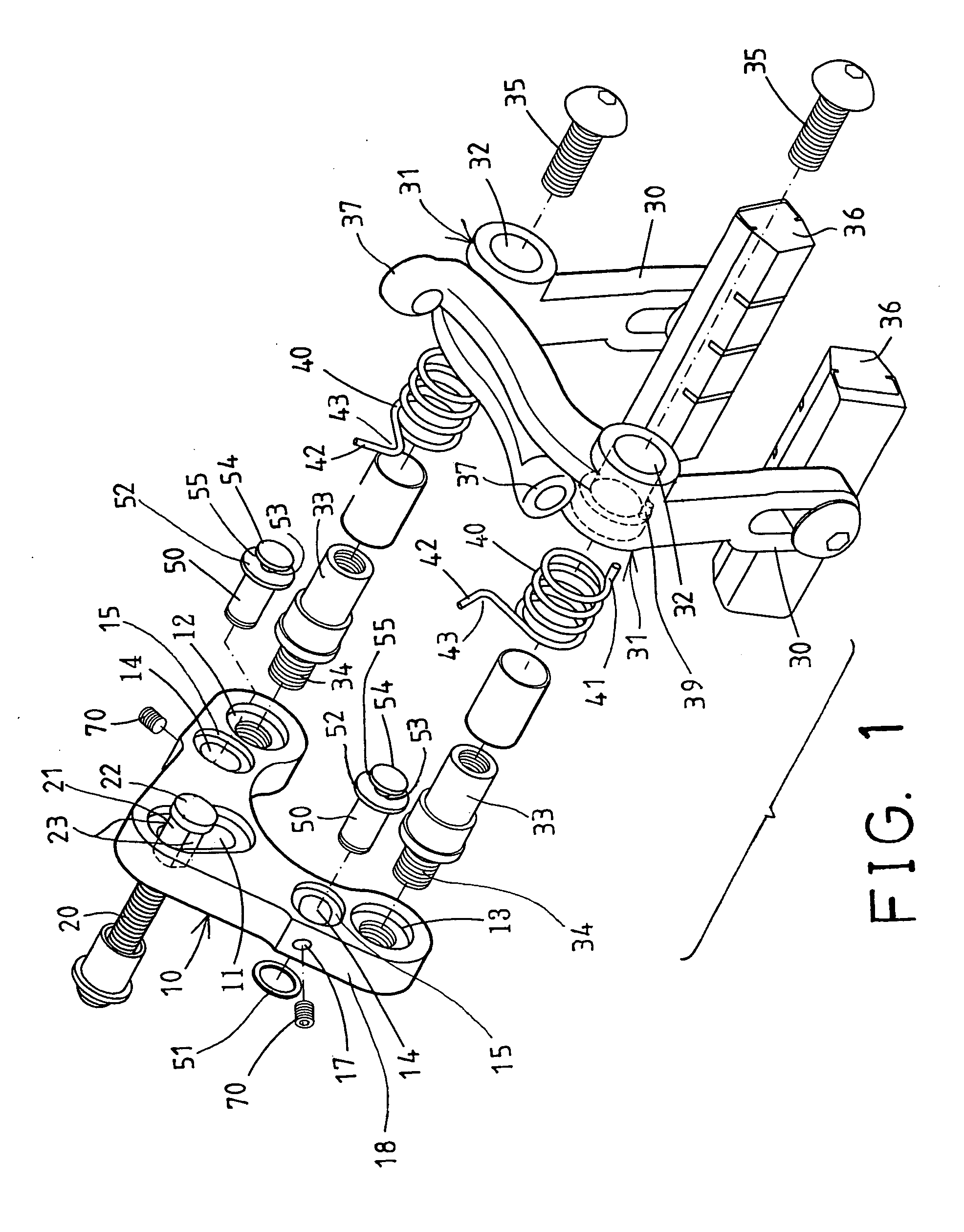
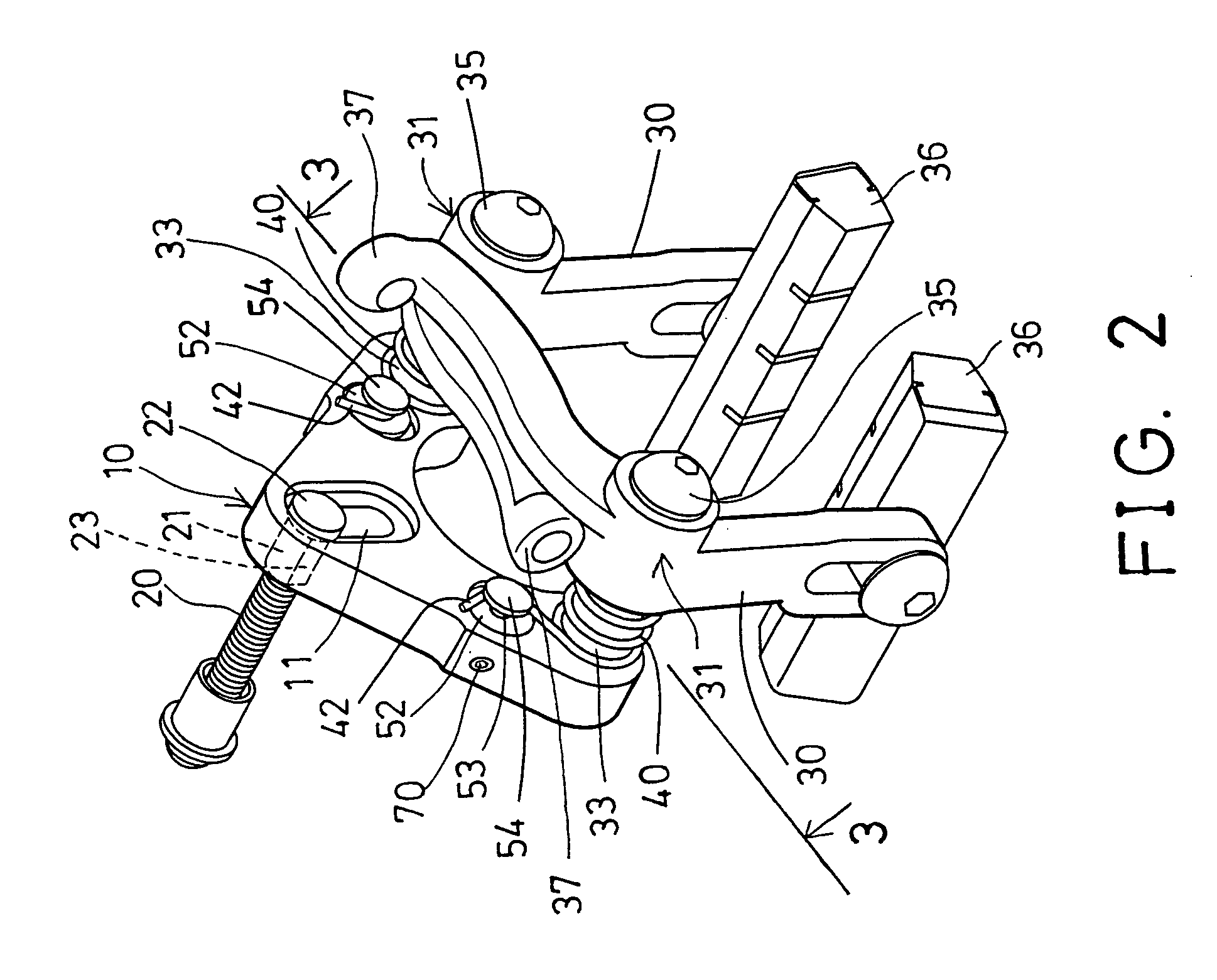
[0025] Referring to the drawings, and initially to FIGS. 1-3, a brake device in accordance with the present invention is primarily provided for attaching to such as cycles, and comprises a holder seat 10 including an oblong hole 11 formed in the middle portion thereof for slidably receiving a fastener 20 which may be secured to fork devices or frames of the cycles (not shown), and thus for adjustably securing the holder seat 10 to the cycles.

[0026] A cap 21 is threaded to one end of the fastener 20, and includes an enlarged head 22 formed or provided on one end of the cap 21, for engaging with the holder seat 10, and for retaining the holder seat 10 to the fastener 20, and for preventing the holder seat 10 from being disengaged from the fastener 20. The cap 21 includes one or more flat side surfaces 23 formed thereon for engaging with the holder seat 10, and for preventing the holder seat 10 from being rotated relative to the cap 21 and the fastener 20.

[0027] The holder seat 10 in...


PUM


Abstract

A brake device includes a holder seat for attaching to cycle, one or more brake arms pivotally attached to the holder seat with shafts and each having a brake shoe for braking the cycle. One or more poles are attached to the holder seat, and each includes a stud, and a coil spring is engaged onto each of the shafts and has one end engaged with the brake arm and the other end engaged with the stud of the pole, to apply a spring biasing force against the brake arm and to recover the brake arm. A fastener may be threaded to the holder seat and engageable with the pole, for moving and adjusting the pole and the coil spring relative to the holder seat.

Description

BACKGROUND OF THE INVENTION [0001] 1. Field of the Invention [0002] The present invention relates to a brake device, and more particularly to a brake device for cycles having one or more spring members that may be adjusted to different resilient or spring biasing forces against brake arms. [0003] 2. Description of the Prior Art [0004] Various kinds of typical brake devices have been developed and attached to cycles, for braking wheels of the cycles, and comprise a pair of brake arms pivotally attached to the fork devices of the cycles, and a pair of brake shoes attached to the brake arms for braking the wheels of the cycles. [0005] For example, U.S. Pat. No. 5,562,185 to Chen, U.S. Pat. No. 5,740,889 to Tsai, U.S. Pat. No. 5,788,019 to Lee et al., U.S. Pat. No. 5,788,020 to Tseng disclose four of the typical brake devices for cycles, and each comprise a pair of brake arms including one end pivotally attached to the fork devices of the cycles, and a pair of brake shoes attached to th...

Claims


Application Information

Patent Timeline
Patent Type & Authority Applications(United States)
IPC IPC(8): B62L1/16
CPCB62L1/16
Inventor TSAI, SHIH FAN
Owner TSAI SHIH FAN
Why Eureka
Try Eureka