Spring-loaded, load sharing polyaxial pedicle screw assembly and method

a technology of pedicle screw and screw head, which is applied in the field of medical devices and assemblies, can solve the problems reducing fatigue resistance, and not allowing the tensioning of the screw head on the top loading pedicle screw, so as to achieve the effect of reducing fatigue resistance and reducing the number of surgeries

Inactive Publication Date: 2007-04-26
CUSTOM SPINE INC
View PDF80 Cites 107 Cited by
  • Summary
  • Abstract
  • Description
  • Claims
  • Application Information

AI Technical Summary

Benefits of technology

[0012] The embodiments herein provide a pedicle screw assembly implant device, which may be used anteriorly or posteriorly, and which is capable of being utilized in surgeries to achieve anterior lumbar interbody fusion, posterior lumbar interbody fusion, transverse lumbar interbody fusion, correct degenerative disc disease, adult and pediatric scoliosis as a fixation device, and posterior cervical fusion.

Problems solved by technology

Surgical procedures treating spinal injuries are one of the most complex and challenging surgeries for both the patient and the surgeon.
However, due to the complexity of the human anatomy, most surgeons must bend the rod (causing notches thereby reducing fatigue resistance) before placing them into two or more non-aligned pedicle screws in order to properly stabilize the pedicle screw assembly within the patient's body.
Additionally, most conventional top loading pedicle screws do not allow for a screw head to be tensioned in a given zone or range of angulations from the fixed bone anchor (i.e., bone screw).
Generally, most artificial discs currently being marketed do not typically offer any resistance at the extreme ranges of motion, and others tend to offer a “dead stop” that may cause implant failure or implant dislodging.
As such, most surgeons would concede that the removal of a failed artificial disc is an extremely undesirable event that is laced with major complications.

Method used


Image

  • Spring-loaded, load sharing polyaxial pedicle screw assembly and method
  • Spring-loaded, load sharing polyaxial pedicle screw assembly and method
  • Spring-loaded, load sharing polyaxial pedicle screw assembly and method

Examples


Embodiment Construction

[0038] The embodiments herein and the various features and advantageous details thereof are explained more fully with reference to the non-limiting embodiments that are illustrated in the accompanying drawings and detailed in the following description. Descriptions of well-known components and processing techniques are omitted so as to not unnecessarily obscure the embodiments herein. The examples used herein are intended merely to facilitate an understanding of ways in which the embodiments herein may be practiced and to further enable those of skill in the art to practice the embodiments herein. Accordingly, the examples should not be construed as limiting the scope of the embodiments herein.

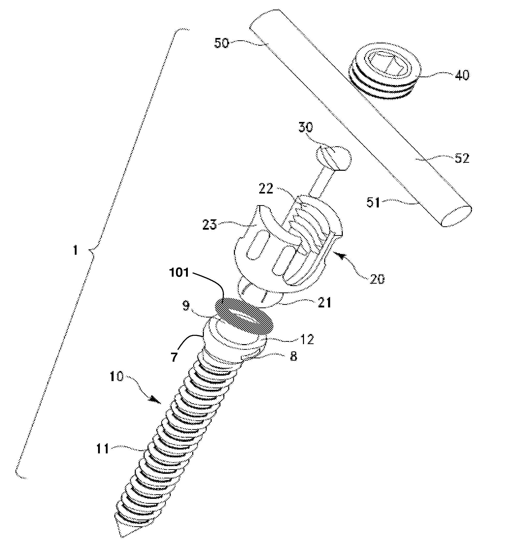
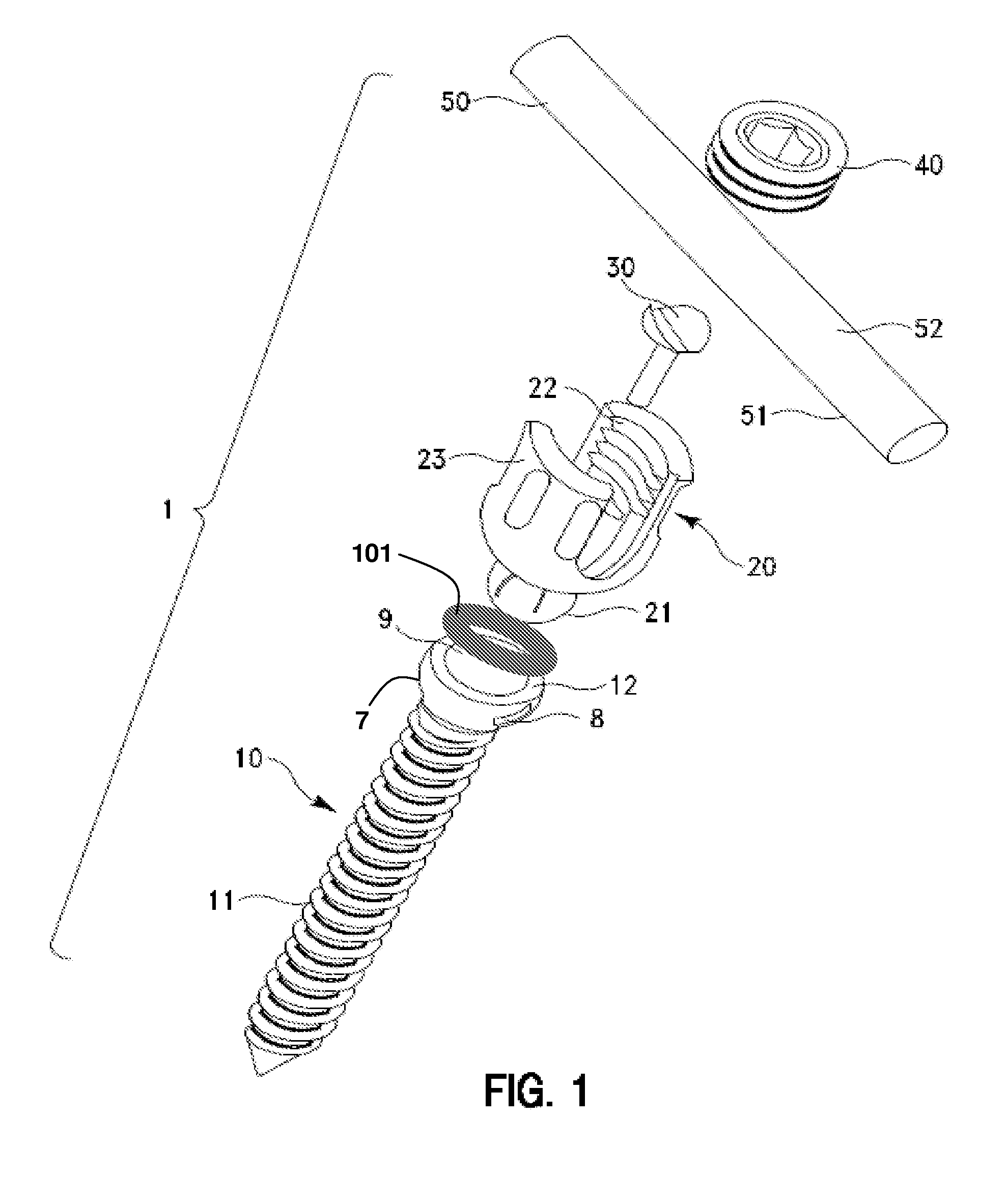
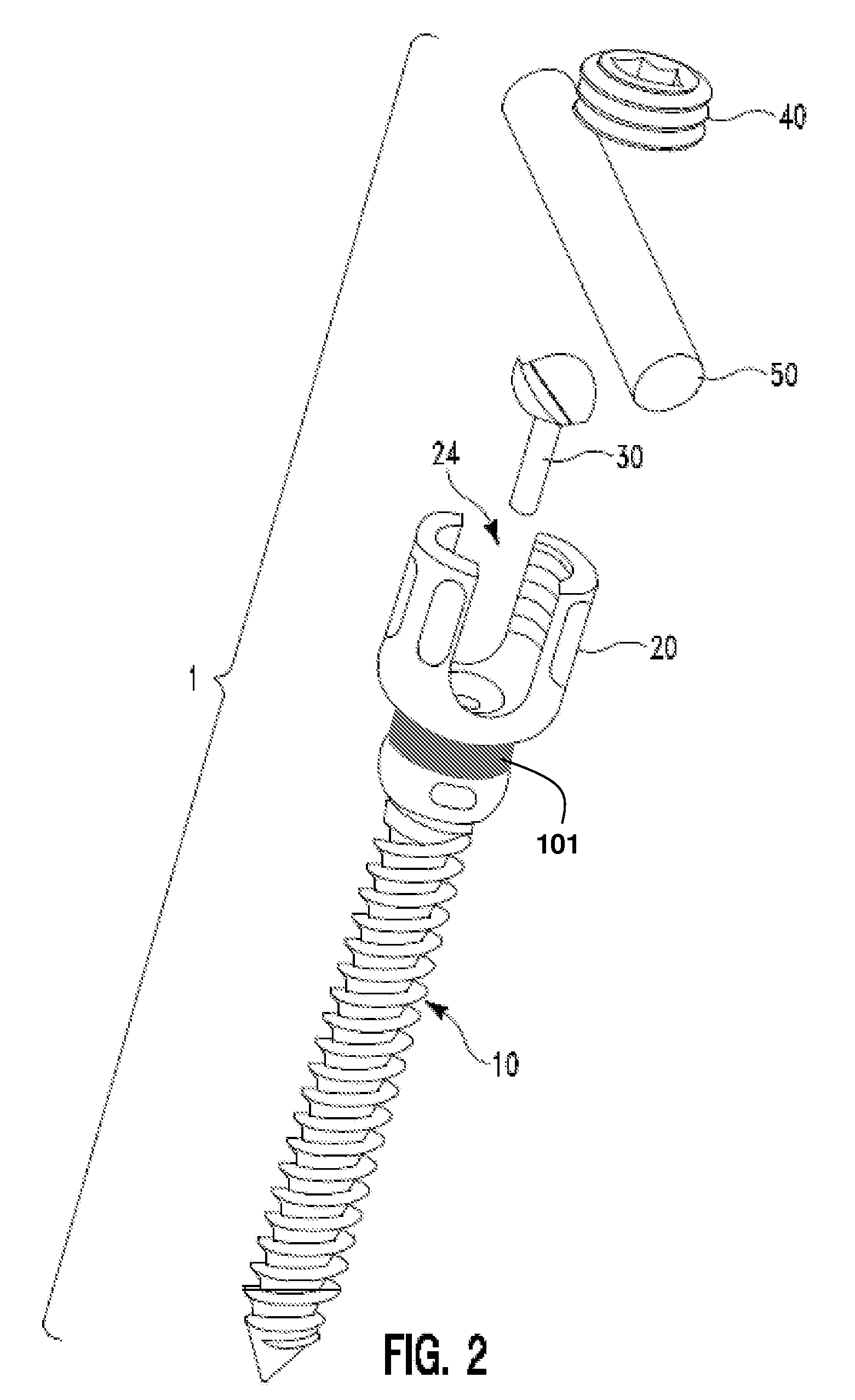
[0039] As mentioned, there remains a need for a new and improved pedicle screw assembly that allows the screw head to be tensioned in a given zone or range of angulations from the fixed bone anchor. The embodiments herein address this need by providing an improved polyaxial pedicle screw devi...


PUM

PropertyMeasurementUnit
tensile resistanceaaaaaaaaaa
flexibleaaaaaaaaaa
fatigue resistanceaaaaaaaaaa

Abstract

An assembly and method thereof comprising a screw head comprising an expandable bulbous end; a fixator component configured for receiving the bulbous end of the screw head; a load sharing mechanism positioned in between the bulbous end of the screw head and the bone fixator component, wherein the load sharing mechanism provides tensile resistance to the screw head; a pin mounted in the screw head; and a blocker adapted to engage the screw head. The screw head comprises a slot configured for receiving a longitudinal member. The load sharing mechanism may comprise any of a wave washer, a collapsible hollow washer, a coiled spring, and a flexible washer. Furthermore, the load sharing mechanism may comprise a washer having an outer surface with a plurality of cutout portions configured therein.

Description

CROSS REFERENCE TO RELATED APPLICATION [0001] This application is a continuation-in-part (CIP) of U.S. patent application Ser. No. 11 / 045,908 filed on Jan. 28, 2005 entitled “Polyaxial Pedicle Screw Assembly” and assigned to Custom Spine, Inc. of Parsippany, N.J., the complete disclosure of which, in its entirety, is herein incorporated by reference, and which claims the benefit of U.S. Provisional Patent Application No. 60 / 548,543 filed on Feb. 27, 2004 and U.S. Provisional Patent Application No. 60 / 565,658 filed on Apr. 2, 2004, the complete disclosures of which, in their entireties, are herein incorporated by reference.BACKGROUND [0002] 1. Technical Field [0003] The embodiments herein generally relate to medical devices and assemblies, and more particularly to an orthopedic surgical implant assembly used in the field of surgical lumbar, thoracic and cervical spine treatment. [0004] 2. Description of the Related Art [0005] Surgical procedures treating spinal injuries are one of th...

Claims


Application Information

Patent Timeline
Patent Type & Authority Applications(United States)
IPC IPC(8): A61F2/30A61B17/70
CPCA61B17/7032Y10T29/49948A61B17/7037
Inventor ABDELGANY, MAHMOUD F.
Owner CUSTOM SPINE INC
Why Eureka
Try Eureka