Total body exercise machine with adjustable railings and/or adjustable incline

a total body exercise machine and adjustable technology, applied in the field of exercise machines, can solve problems such as the inability to provide such a motor

Inactive Publication Date: 2005-06-09
WILKINSON WILLIAM T
View PDF75 Cites 98 Cited by
  • Summary
  • Abstract
  • Description
  • Claims
  • Application Information

AI Technical Summary

Problems solved by technology

Other treadmills, referred to as “manual” treadmills, do not provide such a motor, but rather rely upon the forces generated by the user to move the tread.

Method used


Image

  • Total body exercise machine with adjustable railings and/or adjustable incline
  • Total body exercise machine with adjustable railings and/or adjustable incline
  • Total body exercise machine with adjustable railings and/or adjustable incline

Examples


embodiment 112

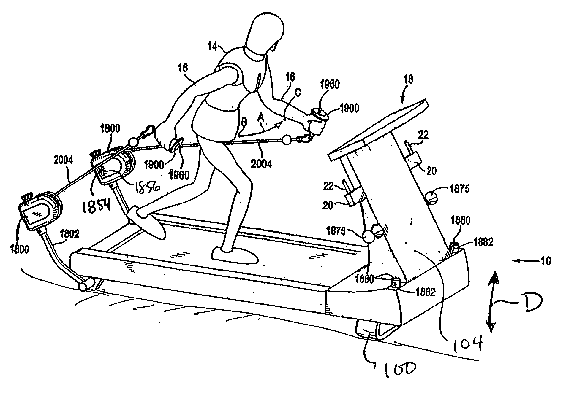
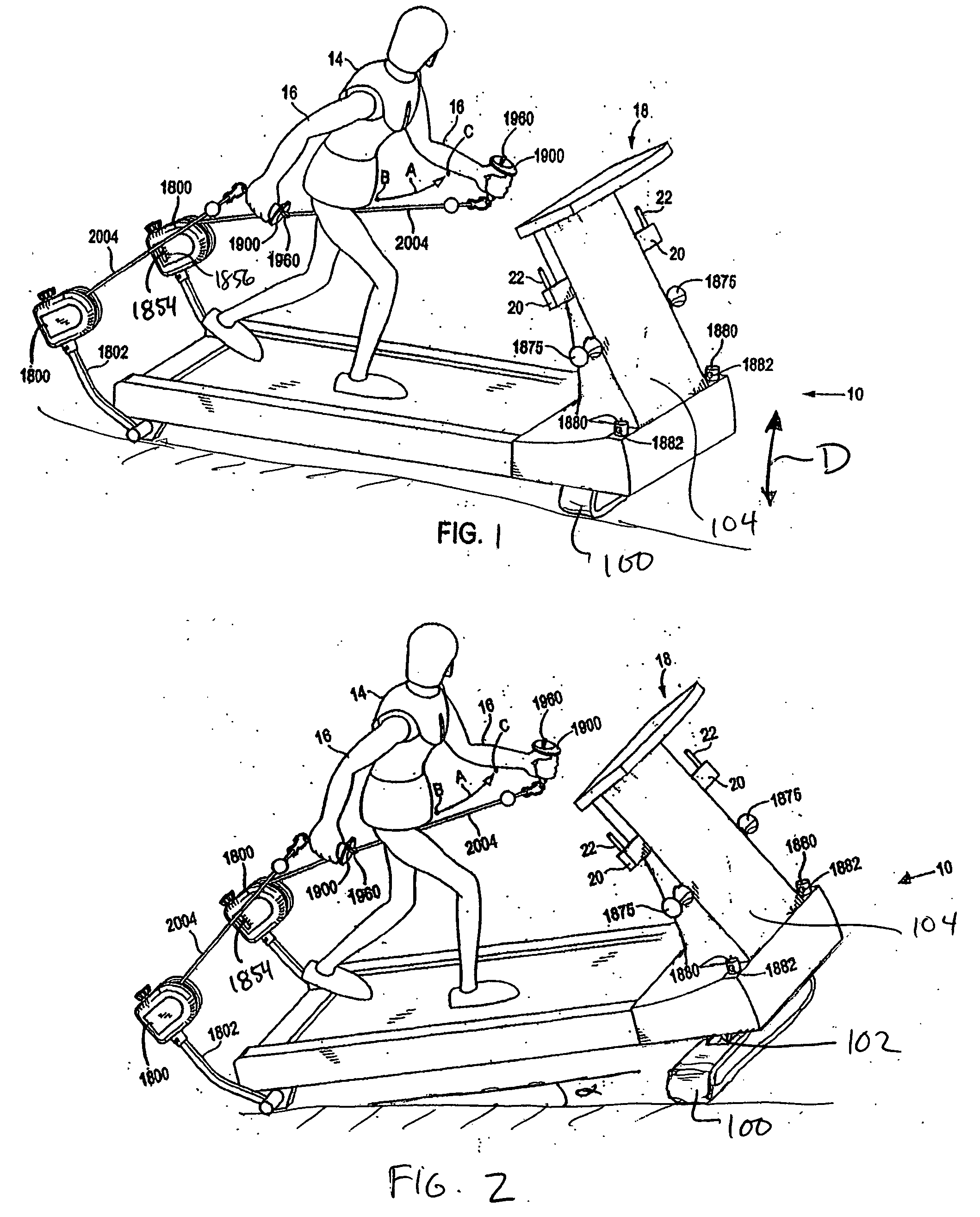
[0070] Referring back to FIG. 15A, a single reel embodiment may be used in conjunction with a lower body exercise machine for providing resistance on the backswing or foreswing of the user, as is amply described in the parent applications. The single reel embodiment 112 shown in FIGS. 15A and 15B is mounted on a mounting arm 600 that provides flexibility in a number of directions. For example, the mounting arm comprises an inner sleeve 602 and an outer sleeve 604. Inner sleeve 602 has a number of channels 606 (representative channel shown in dashed lines) adapted to receive pin 608 which fits through mating a mating hole in outer sleeve 604. This allows length adjustment along arrow L. Machine bracket 612 affixes the mounting arm to the lower body exercise machine. Bracket 612 comprises a pivot pin 614 and a plurality of locking holes 616 through which a pin 618 can be placed to fix the mounting arm at a desired angle relative to the machine. Reel mounting bracket 620 comprises a pi...

embodiment 410

[0075] Changing the length can be accomplished any number of ways, including by putting a number of different attachment points 402a-c on the lower body exercise machine to which the band 404 can be attached, each attachment point a different distance from the user. Another method is to provide a buckle or other type of mechanism 406, known in the art, for changing the length between end 408 of the band closest to the user and the user engagement 1900. Another way is to provide a reel embodiment 410 on which elastic band 412 is wound on one end. In such an embodiment, the reel does not rotate during use, but rather serves as an anchor for the fixed end of the elastic member and an adjustment mechanism for the degree of resistance. The resistance can be adjusted by winding or unwinding the fixed portion of the elastic member onto or off of the reel, thereby changing the length of the free portion of the elastic member that stretched during use. The resistance of the cord to a swing o...


PUM


Abstract

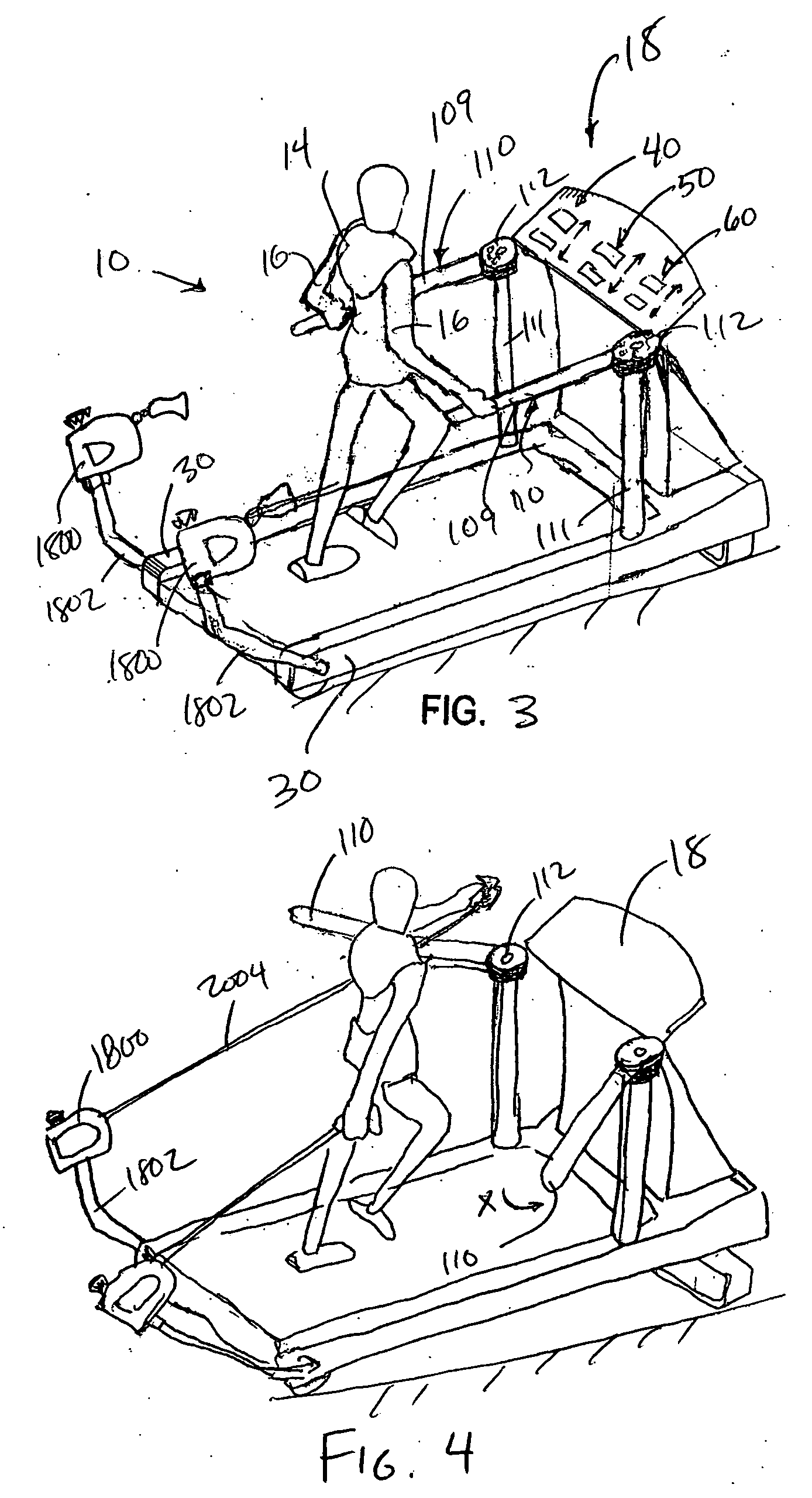
An exercise apparatus comprising a lower body exercise machine, at least one upper body exercise module positioned for engagement by a user of the machine, each module adapted to provide resistance to the user's full natural arm swing. Each module comprises an elongated connector, a user engagement connected to one end of the elongated connector for engaging or being engaged by a body appendage of a user, and a resistance mechanism for resisting a tensile force applied to the end of the elongated connector. The apparatus comprises a mechanism for adjusting the incline of the user platform of the lower body exercise machine and / or a mechanism for adjusting an attached railing between a close position suitable for gripping by the user and a far position sufficiently distant from the close position to prevent interference with the full natural arm swing of the user.

Description

CROSS-REFERENCE TO RELATED APPLICATIONS [0001] This application is a continuation-in-part of U.S. patent application Ser. No. 10 / 611,763, filed Jul. 1, 2003, which is a continuation-in-part of U.S. patent application Ser. No. 10 / 033,108, filed Dec. 28, 2001, and which claims priority from U.S. Provisional Patent Application Ser. No. 60 / 463,534, filed on Apr. 17, 2003. patent application Ser. No. 10 / 033,108 further claims priority from U.S. Provisional Patent Application Ser. No. 60 / 259,293, filed on Dec. 29, 2000. All of the above-named prior applications are hereby incorporated herein by reference.TECHNICAL FIELD [0002] This invention relates to exercise machines, and more particularly to lower body exercise machines, such as but not limited to treadmills, having an upper body exercise component for providing total-body exercise. BACKGROUND OF THE INVENTION [0003] The exercise and fitness industry continues to be an area of high growth, marked by a proliferation of exercise machine...

Claims


Application Information

Patent Timeline
Patent Type & Authority Applications(United States)
IPC IPC(8): A63B21/00A63B21/015A63B21/02A63B21/055A63B22/02A63B22/08A63B23/035A63B23/12
CPCA63B21/00061A63B2022/0652A63B21/00069A63B21/015A63B21/025A63B21/0442A63B21/0552A63B21/0557A63B21/1434A63B21/1438A63B21/1442A63B21/1469A63B21/153A63B22/0012A63B22/0023A63B22/0235A63B23/047A63B2022/0041A63B2208/0204A63B2022/0005A63B22/0605A63B21/00065A63B21/4035A63B21/4019A63B21/4017A63B21/4021A63B22/0005
Inventor WILKINSON, WILLIAM T.
Owner WILKINSON WILLIAM T
Why Eureka
Try Eureka