Dynamic generation of vector graphics and animation of bottom hole assembly

a vector and assembly technology, applied in the direction of cad circuit design, instruments, reradiation, etc., can solve the problems of not being able to easily change the display quality, and not being able to assemble all the bha components, etc., to achieve the effect of reducing the difficulty of reradiation

Inactive Publication Date: 2005-03-24
SCHLUMBERGER TECH CORP
View PDF16 Cites 45 Cited by
  • Summary
  • Abstract
  • Description
  • Claims
  • Application Information

AI Technical Summary

Problems solved by technology

Due to enormous costs associated with drilling a well, it is imperative that the drilling process be carefully planned.
However, it may not be practical to assemble all the BHA components to test all possibilities

Method used


Image

  • Dynamic generation of vector graphics and animation of bottom hole assembly
  • Dynamic generation of vector graphics and animation of bottom hole assembly
  • Dynamic generation of vector graphics and animation of bottom hole assembly

Examples


Embodiment Construction

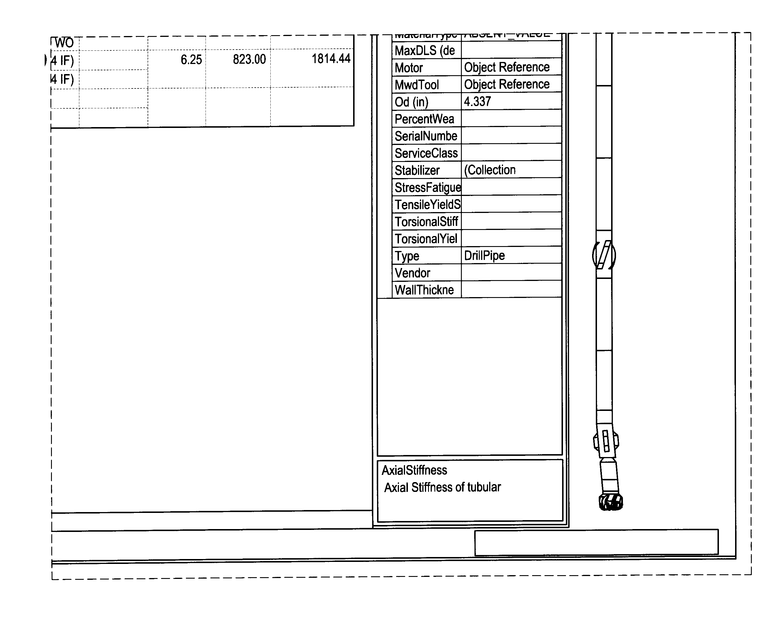
[0024] Embodiments of the invention relate to methods and systems for displaying bottom-hole assembly (BHA), using vector graphics to represent the components of a BHA. VG drawings can be dynamic and interactive. Vector graphics permits a user to manipulate and scale the BHA components according to the relative scale (dimension) of the components, while maintaining the “quality” of the display.

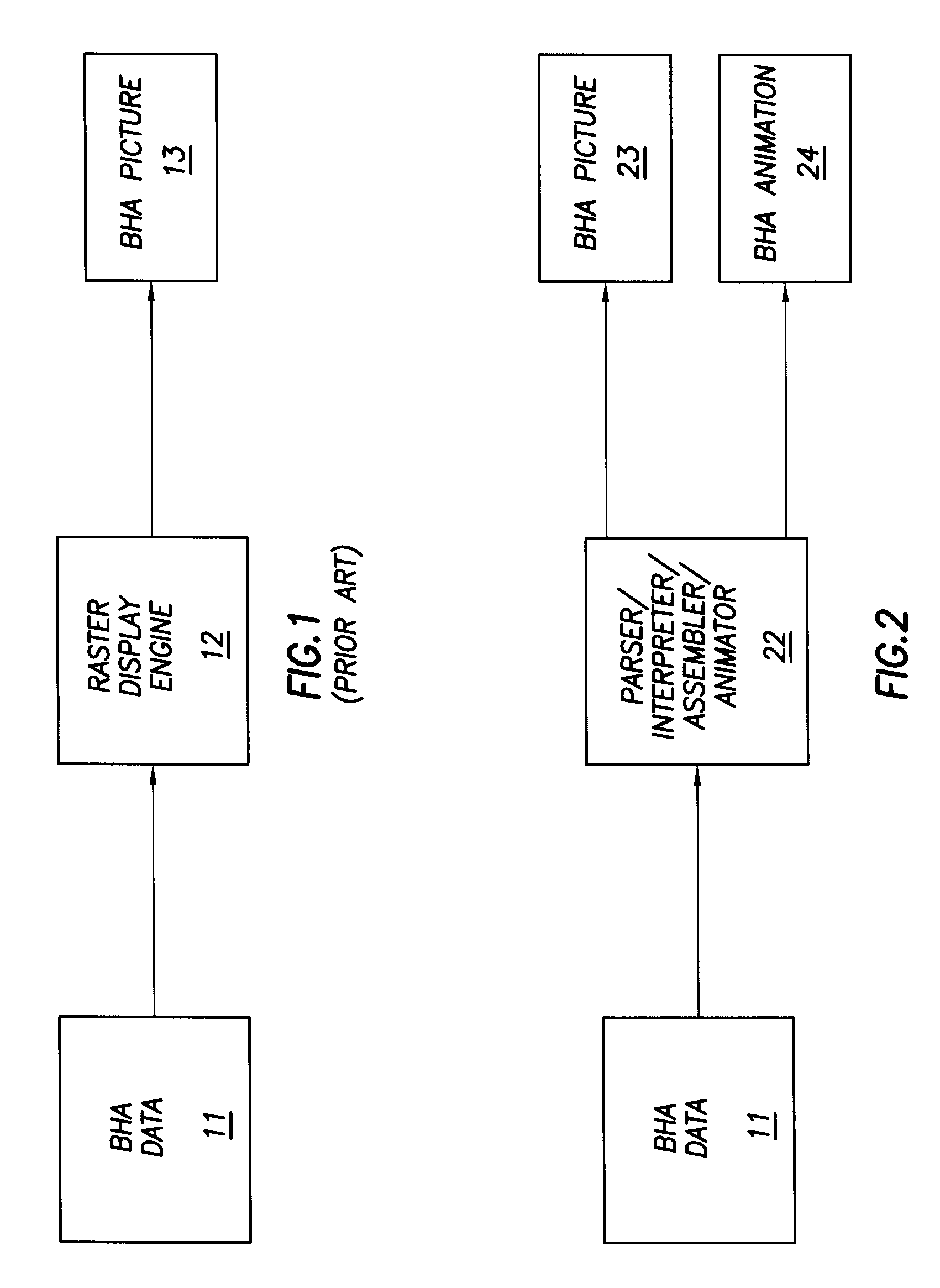
[0025] As noted above and illustrated in FIG. 1, conventional methods display a BHA in bitmap graphics. As shown in FIG. 1, the BHA data 11 is rendered by a graphics display process 12 (e.g., a bitmap or raster graphics display process) to produce a bitmap graphics of the BHA 13. The bitmap picture cannot be scaled or rotated. Every time a new scene is created due to zoom or rotation, the BHA picture needs to be redrawn. Thus, the bitmap pictures cannot be efficiently used to produce animation.

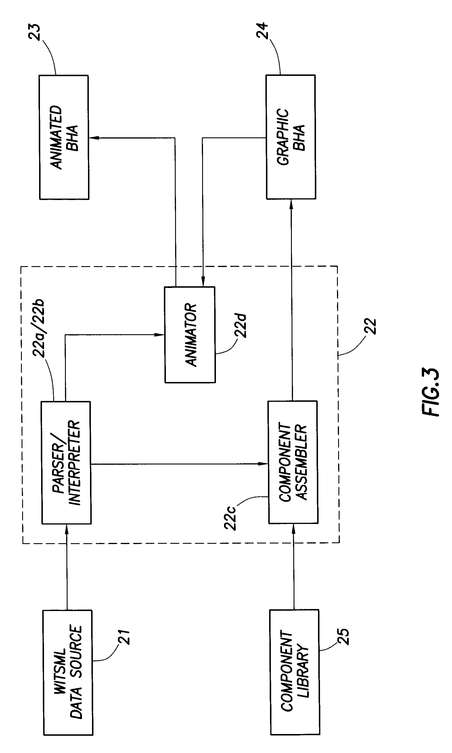
[0026]FIG. 2 illustrates a general scheme for displaying a BHA, using vector graphics and animation...


PUM


Abstract

A method for displaying a bottom-hole assembly (BHA) using vector graphics includes parsing and interpreting BHA source data to produce data packets corresponding to BHA components; assembling the BHA using vector graphics components in a vector graphics library, wherein the vector graphics components represent the BHA components; and displaying the BHA at a selected scale.

Description

CROSS REFERENCE TO RELATED APPLICATIONS [0001] This claims priority, under 35 U.S.C. §119, of a Provisional Application Ser. No. 60 / 500189, filed Sep. 4, 2003. The content of this Provisional Application is incorporated by reference in its entirety.BACKGROUND OF INVENTION [0002] 1. Field of the Invention [0003] The invention relates generally to methods and systems for analyzing data generated in oilfield exploration. More particularly, the invention relates to methods and systems that facilitate the analysis of bottom-hole assembly data. [0004] 2. Background Art [0005] Wells are generally drilled into the ground to recover natural deposits of oil and gas trapped in geological formations. While the well is being drilled or after it is drilled, drillers often investigate the formation and its contents using various sensors, such as resistivity sensors, nuclear magnetic sensors, neutron sensors, gamma ray sensors, etc. These sensors may be lowered into the well on a wireline to take m...

Claims


Application Information

Patent Timeline
IPC IPC(8): G01V1/34G01V11/00G06F30/32
CPCG01V11/00G01V1/34
Inventor GUIDRY, JONATHANCHAU, MINH TRANG
Owner SCHLUMBERGER TECH CORP
Why Eureka
Try Eureka