Hermetic scroll compressor
- Summary
- Abstract
- Description
- Claims
- Application Information
AI Technical Summary
Benefits of technology
Problems solved by technology
Method used
Image
Examples
first embodiment
[0036] First Embodiment
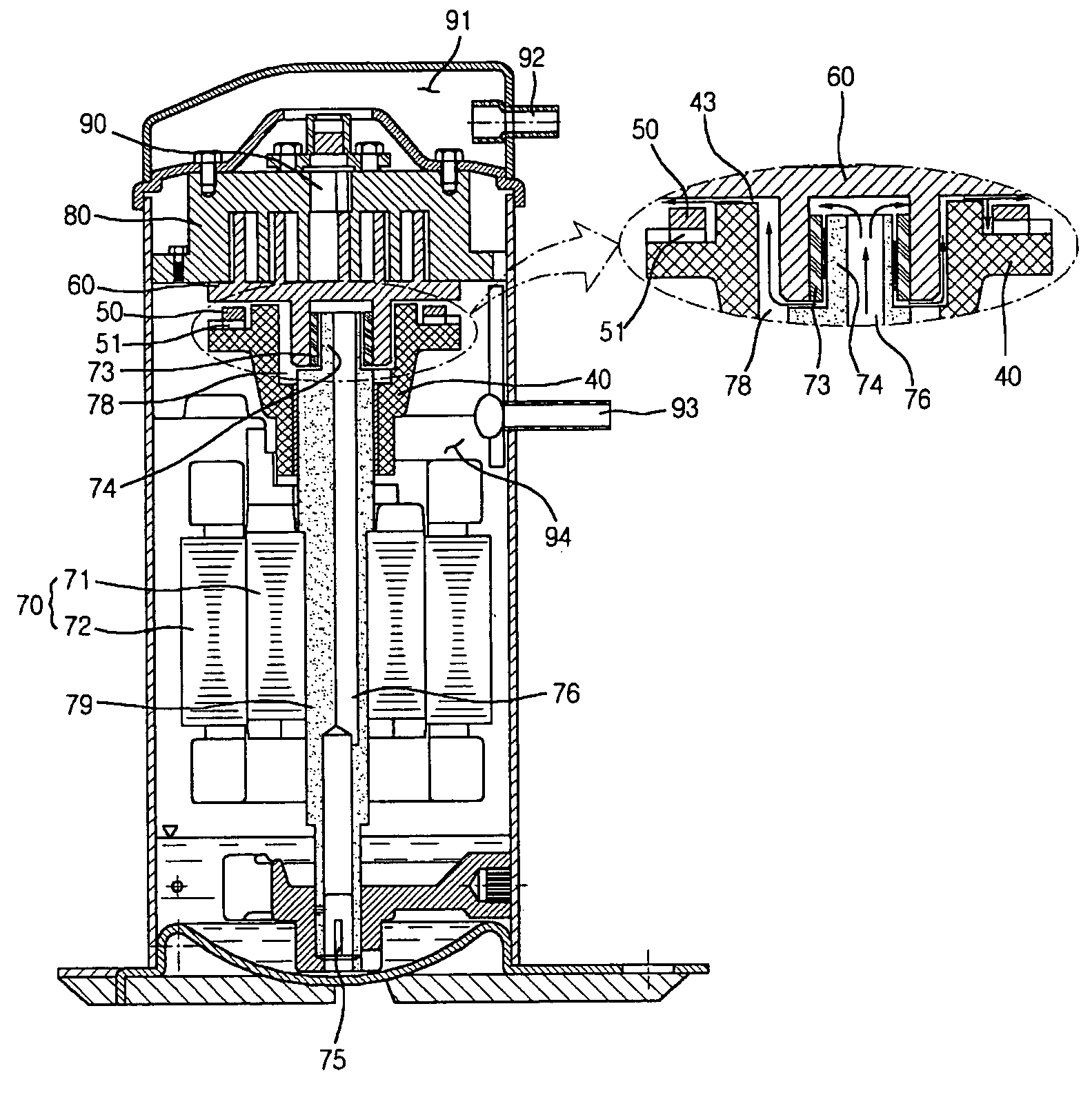
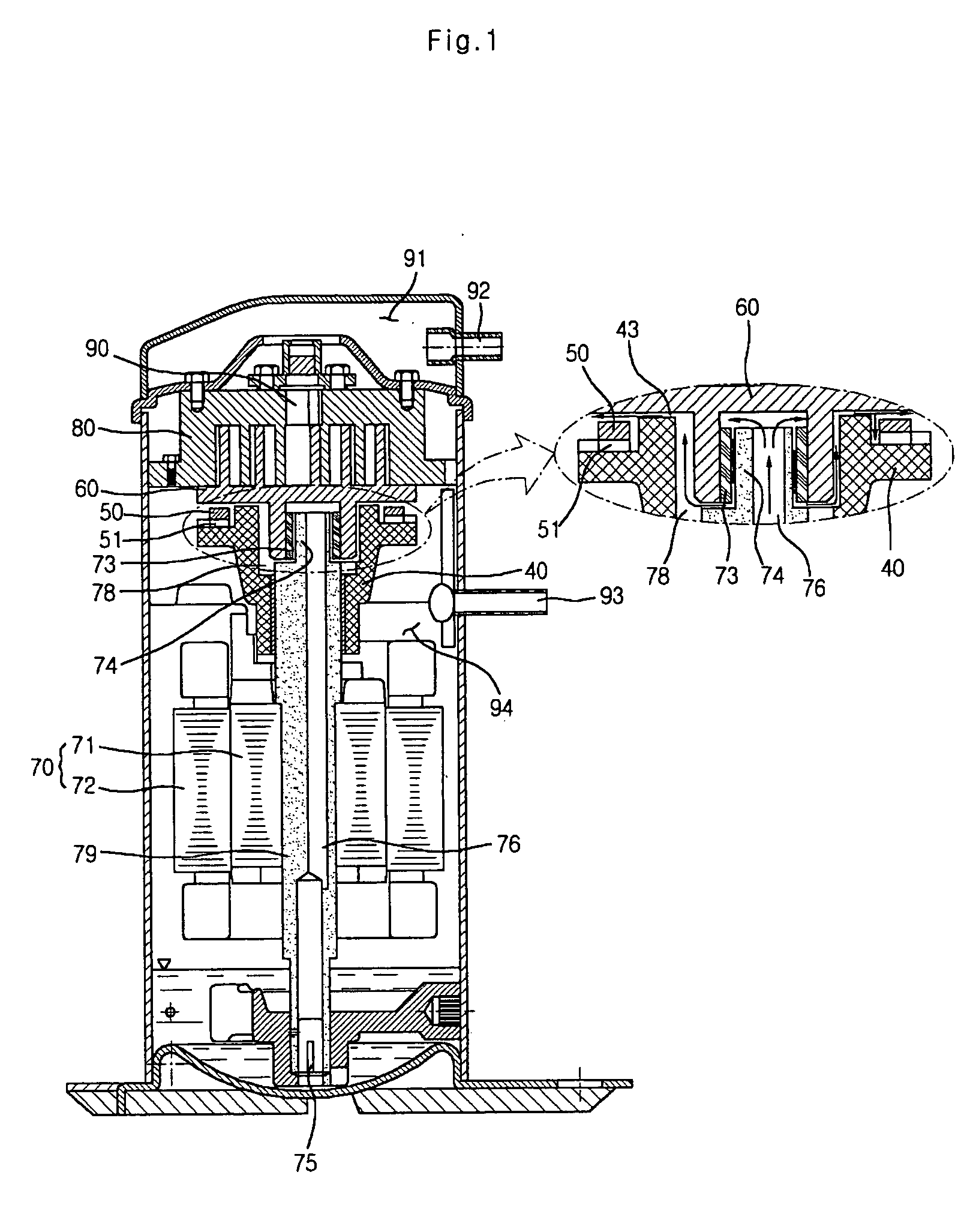
[0037] Referring to FIG. 1, a scroll compressor includes a driving motor 70 having a rotor 71 and a stator 72, a driving shaft 79 which is rotated by rotation of the driving motor 70 and has an eccentric portion 74 at an upper portion thereof, and an upper frame 40 which is fitted to an upper side of the driving shaft 79 so as to support the driving shaft 79 and has an oil pocket 78 at an edge portion of a center groove.
[0038] The scroll compressor further includes a suction portion having a suction pipe 93 for introducing fluid from an outside and a suction chamber 94. In detail, a sliding bush 73 is inserted onto an outer surface of the eccentric portion 74 so as to be surface-contacted with the eccentric portion 74.
[0039] The scroll compressor further includes a scroll compressing portion having an orbiting scroll 60 which is positioned at an upper side of the upper frame 40, for compressing coolant sucked through the suction pipe 93 by an orbiting motion...
second embodiment
[0055] Second Embodiment
[0056]FIG. 4 is a cross-sectional view of a hermetic scroll compressor according to another embodiment of the present invention.
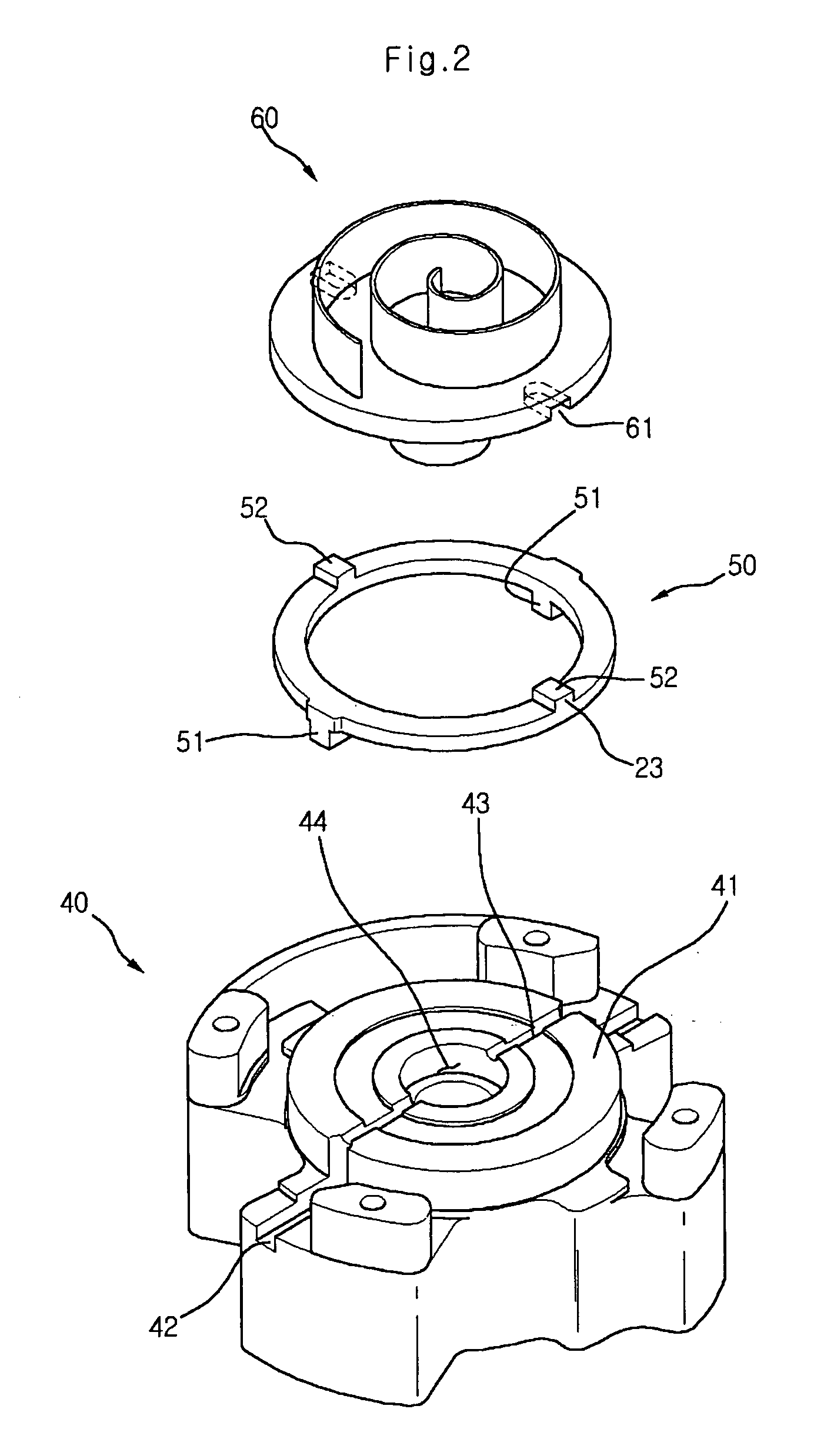
[0057] Referring to FIG. 5, the upper frame 40 according to the present invention comprises a thrust surface 41 which is contacted with a lower surface of an orbiting scroll 60, a lower key groove 42 which is accommodated in an Oldham ring (not shown) so as to be linearly reciprocated, and an oil pocket 44 formed at a center portion of the upper frame 40 so that the oil is accommodated therein.
[0058] In order for the oil from the oil pocket 44 to be run to the lower key 42, there is provided an oil hole 45 formed to penetrate from one end to the other end of the lower key 42.
[0059]FIG. 5 is a perspective view of an upper frame having an oil hole according to the present invention, and FIG. 6 is a plan view of the upper frame.
[0060] Referring to FIGS. 5 and 6, the oil hole 45 of the present invention is formed at a desired depth f...
third embodiment
[0062] Third Embodiment
[0063]FIG. 7 is a cross-sectional view of a scroll compressor according to yet another embodiment of the present invention.
[0064] Referring to FIG. 7, an upper frame of a scroll compressor according to the present invention comprises a oil groove 43 formed at an upper side surface thereof, and an oil hole 45 formed at a position which is below a bottom surface of the oil groove 43 in a desired length.
[0065] Therefore, the oil in the oil pocket 44 is run along the oil groove 43 and the oil hole 45 to the lower key groove 42.
[0066]FIG. 8 is a perspective view of an upper frame of the scroll compressor according to the present invention, and FIG. 9 is a plan view of the upper frame.
[0067] Referring to FIGS. 8 and 9, the oil accumulated in the oil pocket 44 is moved along the oil hole 45 to the lower key groove 42. Thus, the oil can be more rapidly spread in comparison with in the related art scroll compressor in which the oil is spread through the thrust surf...
PUM
 Abstract
Description
Claims
Application Information
 - R&D
- Intellectual Property
- Life Sciences
- Materials
- Tech Scout
- Unparalleled Data Quality
- Higher Quality Content
- 60% Fewer Hallucinations
Browse by: Latest US Patents, China's latest patents, Technical Efficacy Thesaurus, Application Domain, Technology Topic, Popular Technical Reports.
© 2025 PatSnap. All rights reserved.Legal|Privacy policy|Modern Slavery Act Transparency Statement|Sitemap|About US| Contact US: help@patsnap.com


