
Display device with narrow frame

Active Publication Date: 2015-02-12
TCL CHINA STAR OPTOELECTRONICS TECH CO LTD
View PDF25 Cites 0 Cited by
  • Summary
  • Abstract
  • Description
  • Claims
  • Application Information

AI Technical Summary

Benefits of technology

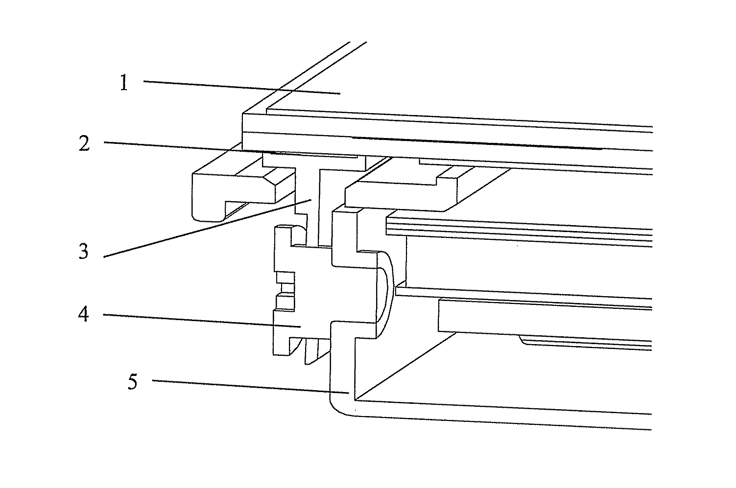
[0007]To solve the above-mentioned problem of shadows caused by the shielding from a hook membe

Problems solved by technology

However, when the BM of the display panel is narrowed to e.g. 3 mm or even smaller, the above-mentioned method is no longer applicable.
When the

Method used


Image

  • Display device with narrow frame
  • Display device with narrow frame
  • Display device with narrow frame

Examples


Example

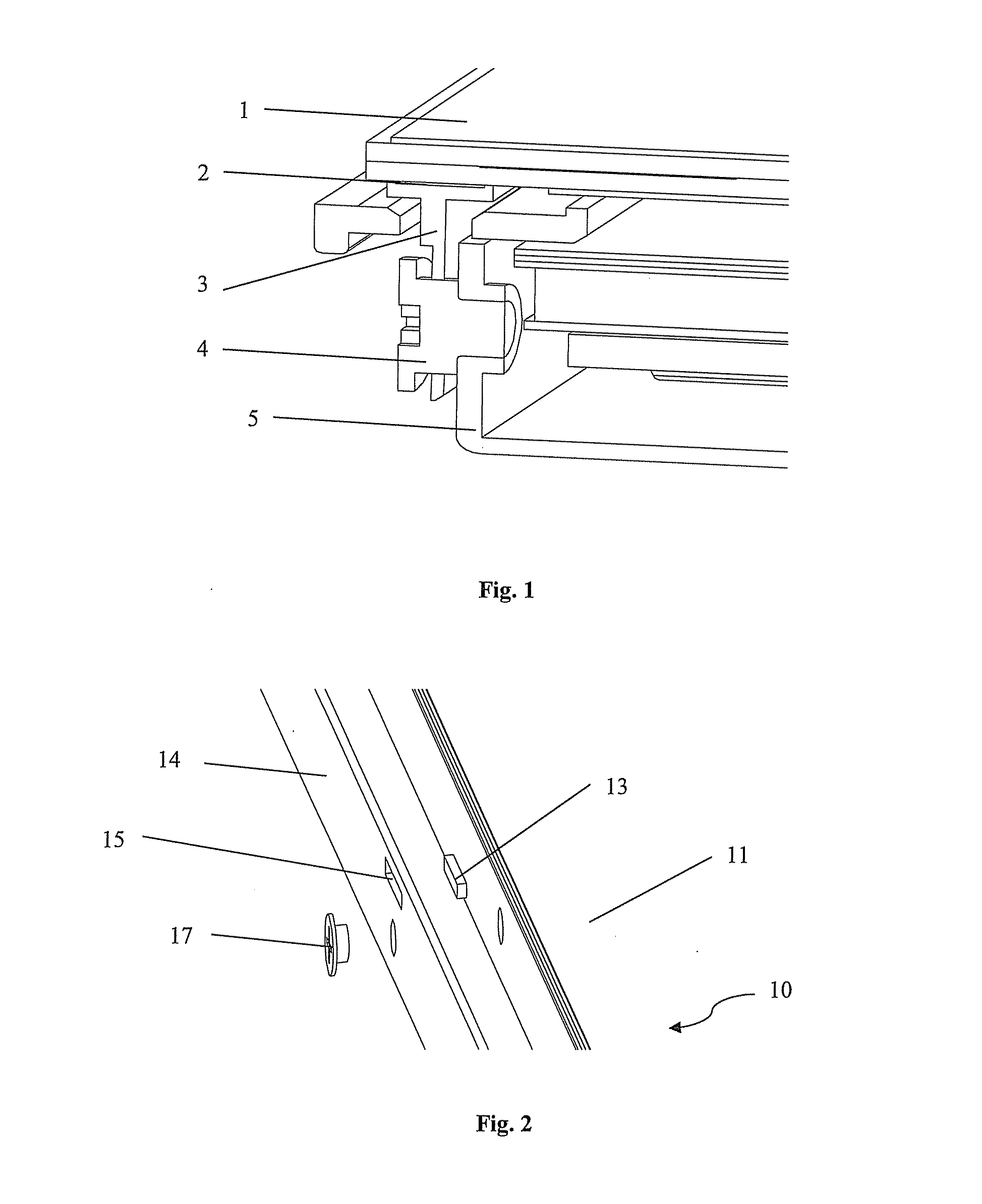
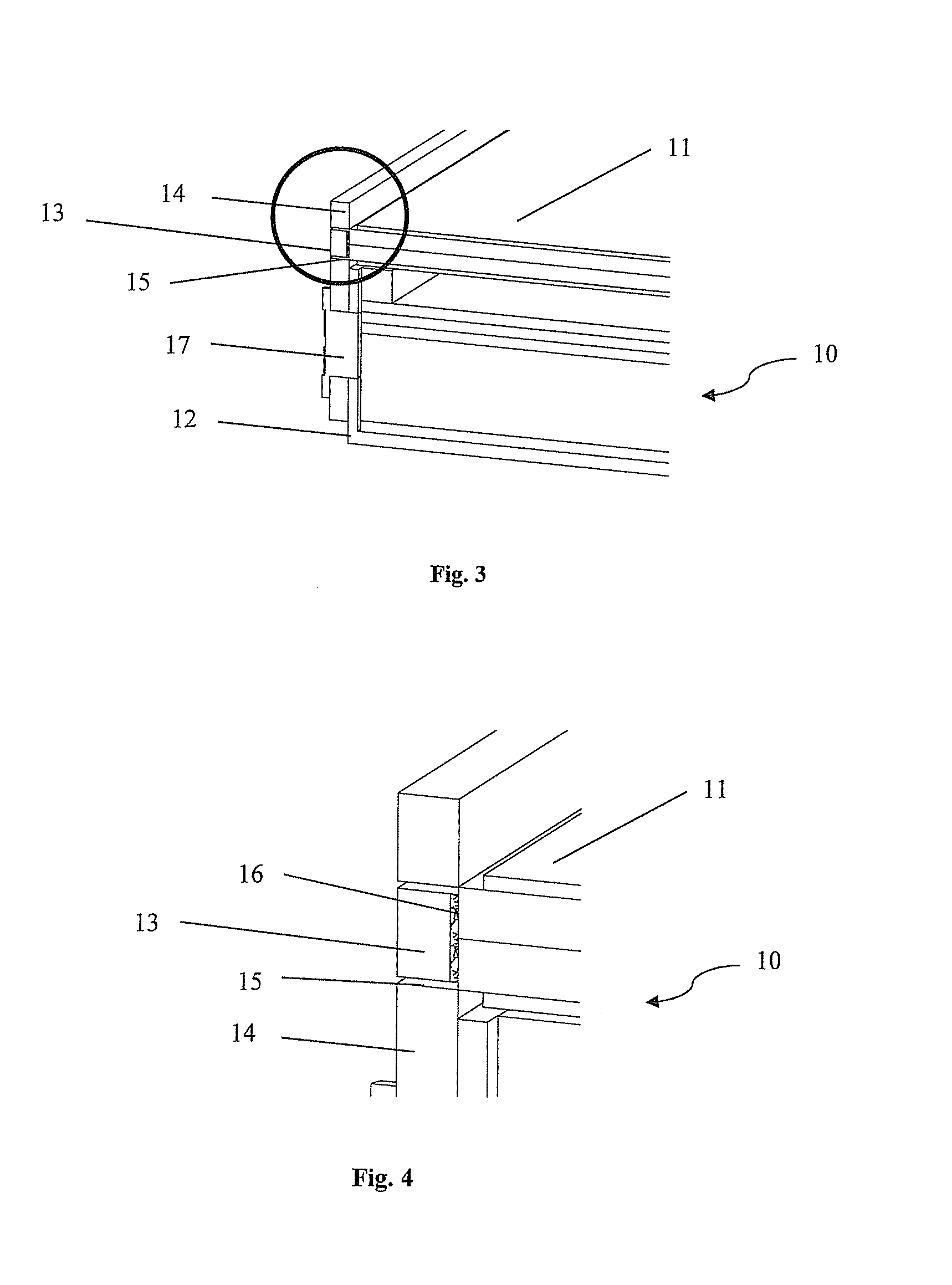
[0033]FIGS. 2 to 5 show a display 10 according to a first embodiment of the present disclosure. In these drawings, FIG. 2 schematically shows the display 10 in an exploded state, and FIGS. 3 and 4 schematically shows the display 10 in an assembled state, wherein FIG. 4 shows the details of the circled portion in FIG. 3.

[0034]The display 10 according to the present disclosure includes a plate-like frame 14 functioning as a support. A through slot 15 extending through the frame 14 along its thickness direction is formed in the frame 14.

[0035]The display 10 further includes a display panel 11 to be assembled together with the frame 14. The display panel 11 may be a liquid crystal display panel, and includes a color filter substrate and an array substrate. In the assembled state, the frame 14 is arranged as being approximately vertical to the plane of the display panel 11, and the through slot 15 of the frame 14 extends longitudinally along the side edge of the display panel 11.

[0036]Th...

Example

[0039]FIGS. 6 to 11 show a display 10′ according to a second embodiment of the present disclosure.

[0040]FIG. 6 shows a display panel 11′ of the display 10′. The display panel 11′ includes a color filter substrate and an array substrate. A projection 18 protruding outwardly is formed at the side edge of the display panel 11′. The projection 18 extends from the display panel 11′ and is integrated therewith. The projection 18 extends longitudinally along the edge of the display panel 11′, and can have a cross section of square or oblong. As shown in FIG. 6, three to six projections 18 can be provided at one and the same edge of the display panel 11′.

[0041]FIG. 7 shows the details of the circled portion in FIG. 6. In the example shown in FIG. 7, both the color filter substrate and the array substrate of the display panel 11′ are provided with a corresponding protruding portion. The two protruding portions faun the projection 18 together.

[0042]FIG. 8 schematically shows the display 10′ i...


PUM


Abstract

The present disclosure relates to the technical field of display, and particularly relates to a display with an improvide 4d frame structure. The present disclosure proposes a narrow frame display, including a display panel having a protruding portion on at least one side edge thereof, a back plate located on one side of the display panel, and a frame including a plate body with a through slot. The frame is arranged vertical to the display panel and fixed on the back plate, and the protruding portion is inserted into the through slot. With this structure of the frame, a hook member used in the prior art can be omitted, so that the shadows caused by shielding of the hook member would be generated no longer. Therefore, the display of the present disclosure can effectively eliminate shadows caused by shielding of the hook member in the prior art. Meanwhile, it is unnecessary to occupy the space of the rear side of the display panel, so that the frame of the display can be further narrowed.

Description

FIELD OF THE INVENTION[0001]The present disclosure relates to the technical field of display, and particularly relates to a display with a relatively narrow frame structure.BACKGROUND OF THE INVENTION[0002]A “narrow frame” of a television indicates that no obvious frame is used to cover a display panel of the television, so that the appearance of the television is simple and fashionable. With the simple and fashionable appearance, the narrow frame television becomes a development trend of liquid crystal televisions.[0003]For the narrow frame structure used in the prior art, generally no obvious frame is arranged on three sides of the television. This is achieved dependent on a Gate On Array (GOA) technology, namely, a gate circuit is directly formed on an array substrate of the display panel, so that a traditional external Gate IC can be avoided. In addition, no additional chip on film (COF) is necessary for circuit wiring, so that there is no need to provide a space on the side of ...

Claims


Application Information

Patent Timeline
IPC IPC(8): H05K5/00H05K5/02H05K7/02
CPCH05K5/0017H05K5/0217H05K7/02H05K5/02
Inventor LI, DEHUATANG, GUOFUCHEN, SHIH HSIANGHSIAO, YUCHUN
Owner TCL CHINA STAR OPTOELECTRONICS TECH CO LTD
Learn More