Extended articular surface resurfacing head

a humeral head and articular surface technology, applied in the field of prosthetic implants, can solve the problems of conventional humeral head resurfacing implants not accommodating patients with inadequate rotator cuff muscles, damage or defective external surfaces of humeral heads, and inability to articulate between implants

Inactive Publication Date: 2005-03-24
BIOMET MFG CORP
View PDF34 Cites 184 Cited by
  • Summary
  • Abstract
  • Description
  • Claims
  • Application Information

AI Technical Summary

Problems solved by technology

It is not uncommon for the exterior surface of the humeral head to be damaged or defective.
Conventional humeral head resurfacing implants fail to accommodate patients having inadequate rotator cuff muscles.
Specifically, conventional implants do not permit articulation between the implant and the concave undersurface of the coracoacromial arch of the scapula, the coracoacromial arch being a structural component of the shoulder comprising the coracoacromial ligament, coracoid process, and acromion.

Method used


Image

  • Extended articular surface resurfacing head
  • Extended articular surface resurfacing head
  • Extended articular surface resurfacing head

Examples


Embodiment Construction

[0016] The following description of the preferred embodiments is merely exemplary in nature and is in no way intended to limit the invention, its application, or uses.

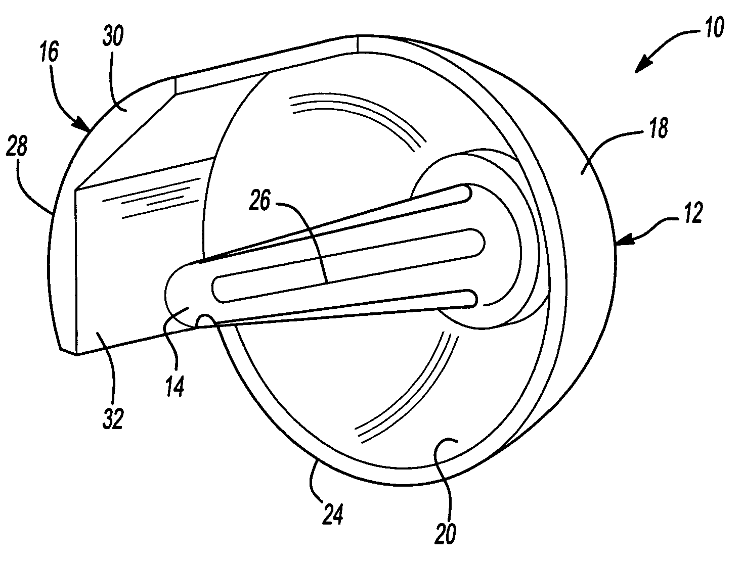
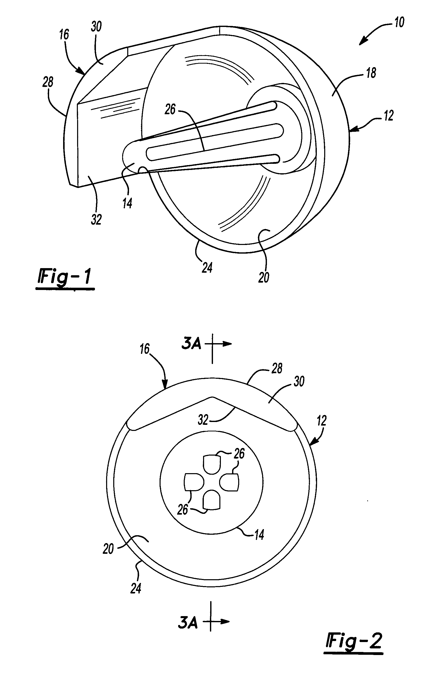
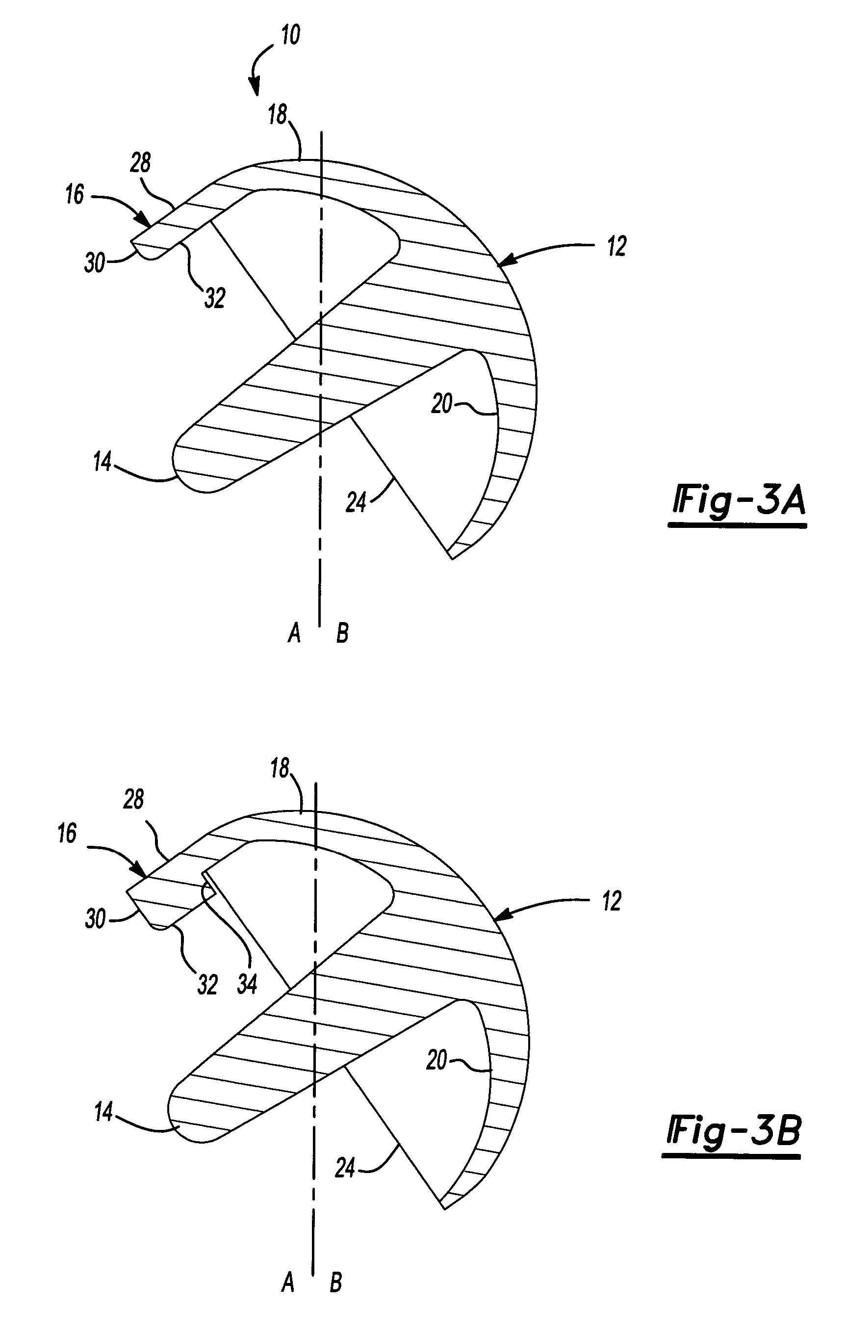
[0017] With initial reference to FIGS. 1 through 3, a resurfacing implant according to the present invention is illustrated and identified at reference numeral 10. The implant 10 is typically divided into, as illustrated in FIG. 3, a lateral region A and a medial region B, which is in relation to the implant position in the patient. The implant 10 generally includes a resurfacing head 12, an anchoring device or stem 14, and an extended surface 16. The extended surface 16 may be located in the lateral region A, as illustrated, or at any other position about a periphery of the head 12. The head 12 includes an exterior surface 18 and an interior surface 20 opposite the exterior surface 18. The exterior surface 18 is generally convex, or dome-shaped, and smooth. The interior surface 20 is generally concave.

[0018] The int...


PUM

PropertyMeasurementUnit
biocompatibleaaaaaaaaaa
diameteraaaaaaaaaa
shapeaaaaaaaaaa

Abstract

A resurfacing implant comprising a head and an extended articulating surface protruding from a portion of the head operable to articulate with at least one of a bone and a ligament. The head has an exterior articulating surface, an interior surface opposite the exterior articulating surface, and an anchoring device extending from the interior surface.

Description

FIELD OF THE INVENTION [0001] The present invention relates to prosthetic implants. In particular, the present invention relates to a humeral resurfacing implant. BACKGROUND OF THE INVENTION [0002] The humerus is the longest and largest bone of the human upper extremity. It is divisible into a body and two extremities. The upper extremity comprises a head that is joined to the body by a constricted portion generally called the neck. The head is nearly hemispherical in form and articulates with the glenoid cavity of the scapula or shoulder blade. The humerus is secured to the scapula by the rotator cuff muscles and tendons. [0003] It is not uncommon for the exterior surface of the humeral head to be damaged or defective. Conventionally, a variety of humeral head resurfacing implants exist for repairing humeral head surfaces. While conventional humeral head resurfacing implants are suitable for their intended uses, such implants are subject to improvement. [0004] Conventional humeral ...

Claims


Application Information

Patent Timeline
Patent Type & Authority Applications(United States)
IPC IPC(8): A61F2/00A61F2/30A61F2/40A61F2/46
CPCA61F2/30767A61F2002/4051A61F2/4003A61F2/4684A61F2002/30176A61F2002/3021A61F2002/30616A61F2002/30688A61F2002/30827A61F2002/30878A61F2002/30906A61F2002/4631A61F2230/0054A61F2230/0067A61F2310/00023A61F2310/00029A61F2310/00407A61F2310/00796A61F2002/4018A61F2002/4025A61F2002/4007A61F2/4014A61F2/30942A61F2002/30593
Inventor WINSLOW, NATHAN A.
Owner BIOMET MFG CORP
Why Eureka
Try Eureka