Articular disc prosthesis and method for implanting the same

a technology of articular discs and prostheses, applied in the field of spinal implants, can solve the problems of affecting the implantation of prior intervertebral disc arthroplasty devices, affecting the implantation of spinal implants,

Inactive Publication Date: 2007-02-20
WARSAW ORTHOPEDIC INC
View PDF49 Cites 272 Cited by
  • Summary
  • Abstract
  • Description
  • Claims
  • Application Information

AI Technical Summary

Benefits of technology

[0015]It is one object of the present invention to provide an improved articular disc prosthesis. It is another object of the present invention to provide an improved method of implanting an articular disc prosthesis within the intervertebral disc space between adjacent vertebral bodies.

Problems solved by technology

Spinal fusion procedures, however, have raised concerns in the medical community that the bio-mechanical rigidity of intervertebral fusion may predispose neighboring spinal motion segments to rapid deterioration.
Such lack of mobility tends to increase stresses on adjacent spinal motion segments.
As discussed above, prior intervertebral disc arthroplasty devices are relatively difficult to implant between adjacent vertebrae.
Such an operation presents a risk of injury to the vertebrae caused by misplacement and / or scratching of the vertebral endplates or other tissue by the anchors.
Such operation also presents a risk of injury resulting from over-distraction of the intervertebral space.
Moreover, prior methods of implanting arthroplasty devices do not reliably position the device at the proper location within the intervertebral disc space.
The articular components associated with prior arthroplasty devices are also prone to wear, particularly in cases where the abutting surface area of the articular joint is relatively small.
Generally, as the abutting surface area of an articular joint is reduced, contact stress is correspondingly increased which may reduce the overall life of the joint.

Method used


Image

  • Articular disc prosthesis and method for implanting the same
  • Articular disc prosthesis and method for implanting the same
  • Articular disc prosthesis and method for implanting the same

Examples


Embodiment Construction

[0034]For the purposes of promoting an understanding of the principles of the invention, reference will now be made to the embodiments illustrated in the drawings and specific language will be used to describe the same. It will nevertheless be understood that no limitation of the scope of the invention is hereby intended, and that any alterations and further modifications in the illustrated devices, and any further applications of the principles of the invention as illustrated herein are contemplated as would normally occur to one skilled in the art to which the invention relates.

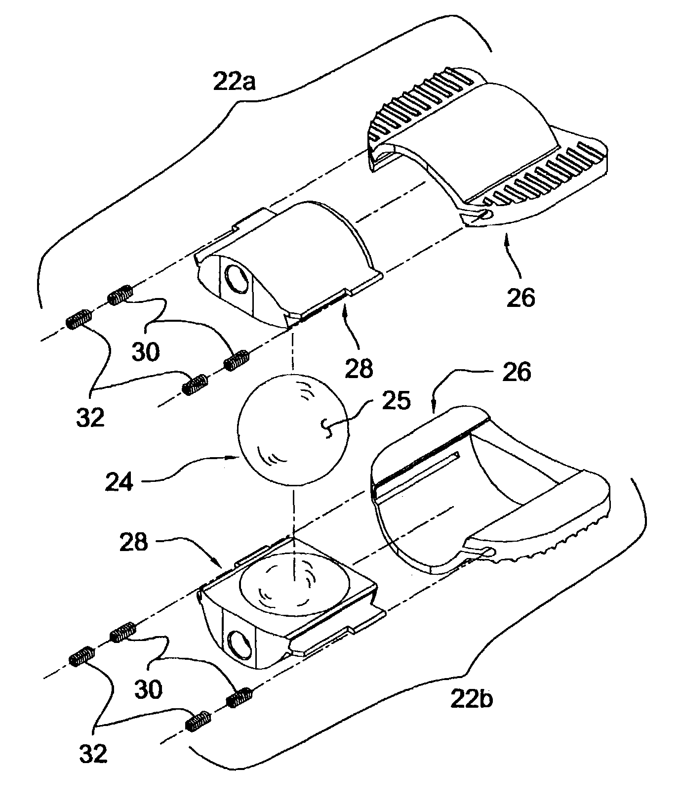
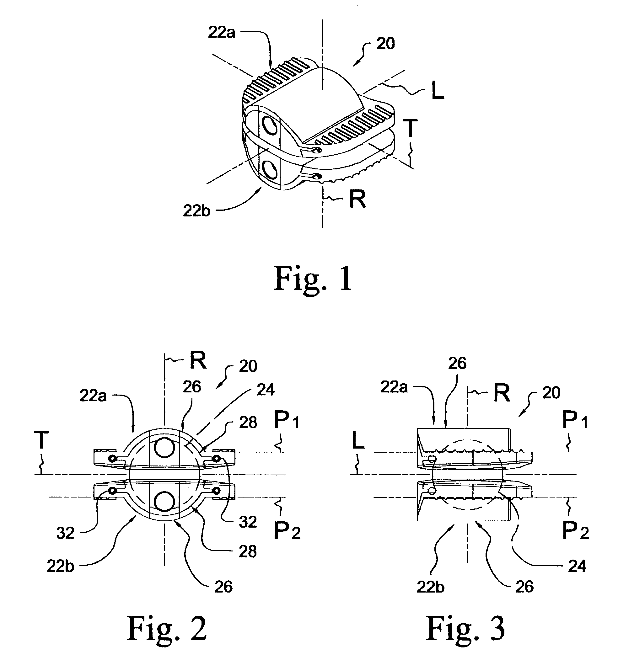
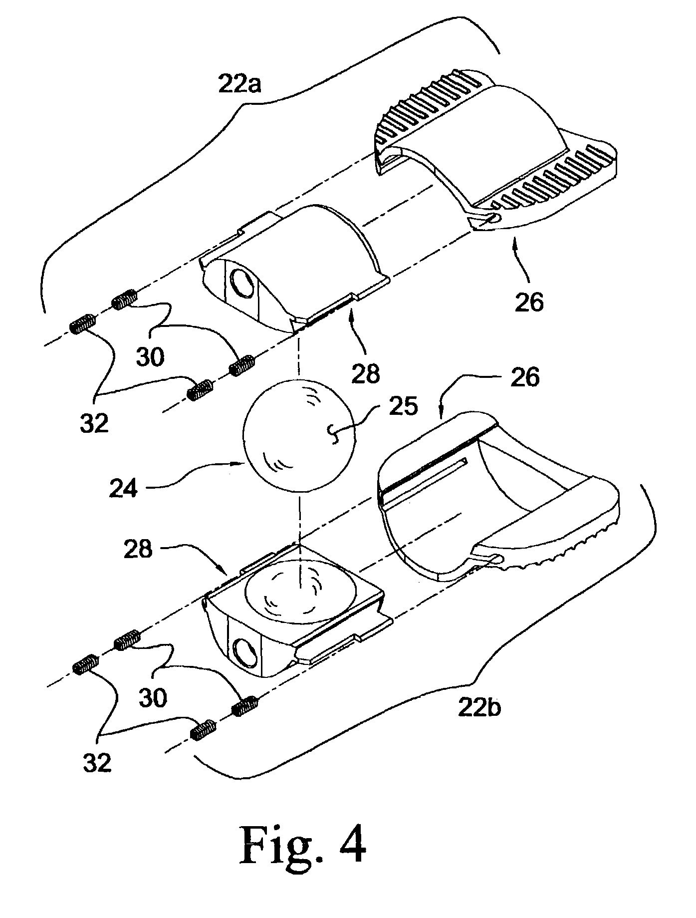
[0035]Referring to FIGS. 1–4, shown therein is an articular disc prosthesis 20 according to one form of the present invention. The disc prosthesis 20 extends generally along a longitudinal axis L and includes an upper articular component 22a, a lower articular component 22b, and an articular ball 24 disposed between the upper and lower articular components 22a, 22b. The articular ball 24 defines a convex ar...


PUM

PropertyMeasurementUnit
taper angleaaaaaaaaaa

Abstract

An articular disc prosthesis and method of implanting the same within an intervertebral space between adjacent vertebral bodies. The prosthesis includes a pair of articular components and an articular ball disposed therebetween. Each of the articular components includes an outer shell portion and a removable inner insert portion. The insert portion includes a concave articular surface sized and shaped to receive a portion of the articular ball to provide articulating motion between the articular components. The outer shell portion includes a central hemi-cylindrical portion, a pair of laterally extending flanges, and an axially extending lip. Following removal of the natural intervertebral disc, a pair of hemi-cylindrical recesses are formed along a central region of the adjacent vertebral bodies to a predetermined depth. The prosthesis is implanted within the prepared disc space by axially displacing the hemi-cylindrical central portions of the articular components along the hemi-cylindrical recesses in the vertebral bodies. The lateral flanges and the axial lip of the articular components bear against the endplates of the adjacent vertebral bodies to stabilize the prosthesis and to prevent subsidence.

Description

CROSS REFERENCE TO RELATED APPLICATIONS[0001]The present application claims the benefit of Provisional Application Ser. No. 60 / 375,354 filed on Apr. 25, 2002, the contents of which are hereby incorporated by reference in their entirety.FIELD OF THE INVENTION[0002]The present invention relates generally to the field of spinal implants, and more particularly relates to an articular disc prosthesis and method of implantation for use in the total or partial replacement of a natural intervertebral disc.BACKGROUND OF THE INVENTION[0003]In the treatment of diseases, injuries or malformations affecting spinal motion segments, and especially those affecting disc tissue, it has long been known to remove some or all of a degenerated, ruptured or otherwise failing disc. In cases involving intervertebral disc tissue that has been removed or is otherwise absent from a spinal motion segment, corrective measures are indicated to insure the proper spacing of the vertebrae formerly separated by the r...

Claims


Application Information

Patent Timeline
Patent Type & Authority Patents(United States)
IPC IPC(8): A61F2/44A61B17/56A61F2/00A61F2/30A61F2/46
CPCA61F2/4425A61F2310/00796A61F2002/30242A61F2002/30383A61F2002/30433A61F2002/30507A61F2002/30604A61F2002/30614A61F2002/30662A61F2002/30845A61F2002/30879A61F2002/30891A61F2002/443A61F2002/4622A61F2220/0025A61F2220/0041A61F2230/0071A61F2310/00017A61F2310/00023A61F2310/00029A61F2310/00179A61F2/4611
Inventor EISERMANN, LUKASRAY, III, EDDIE F.
Owner WARSAW ORTHOPEDIC INC
Why Eureka
Try Eureka