Intra-articular joint replacement

a technology of intraarticular joint and prosthesis, which is applied in the direction of prosthesis, shoulder joints, osteosynthesis devices, etc., can solve the problems of pain to patients, dislocation of prosthesis, and gradual subsidence of interpositional implants within the humeral metaphysis

a technology of intraarticular joint and prosthesis, which is applied in the direction of prosthesis, shoulder joints, osteosynthesis devices, etc., can solve the problems of pain to patients, dislocation of prosthesis, and gradual subsidence of interpositional implants within the humeral metaphysis

US20090287309A1Inactive Publication Date: 2009-11-19TORNIER SA SAINT ISMIER

Image

  • Intra-articular joint replacement
  • Intra-articular joint replacement
  • Intra-articular joint replacement

Examples


Embodiment Construction

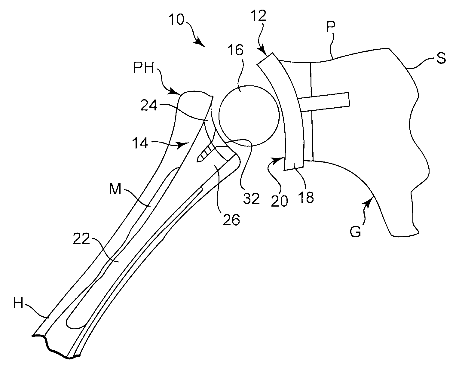
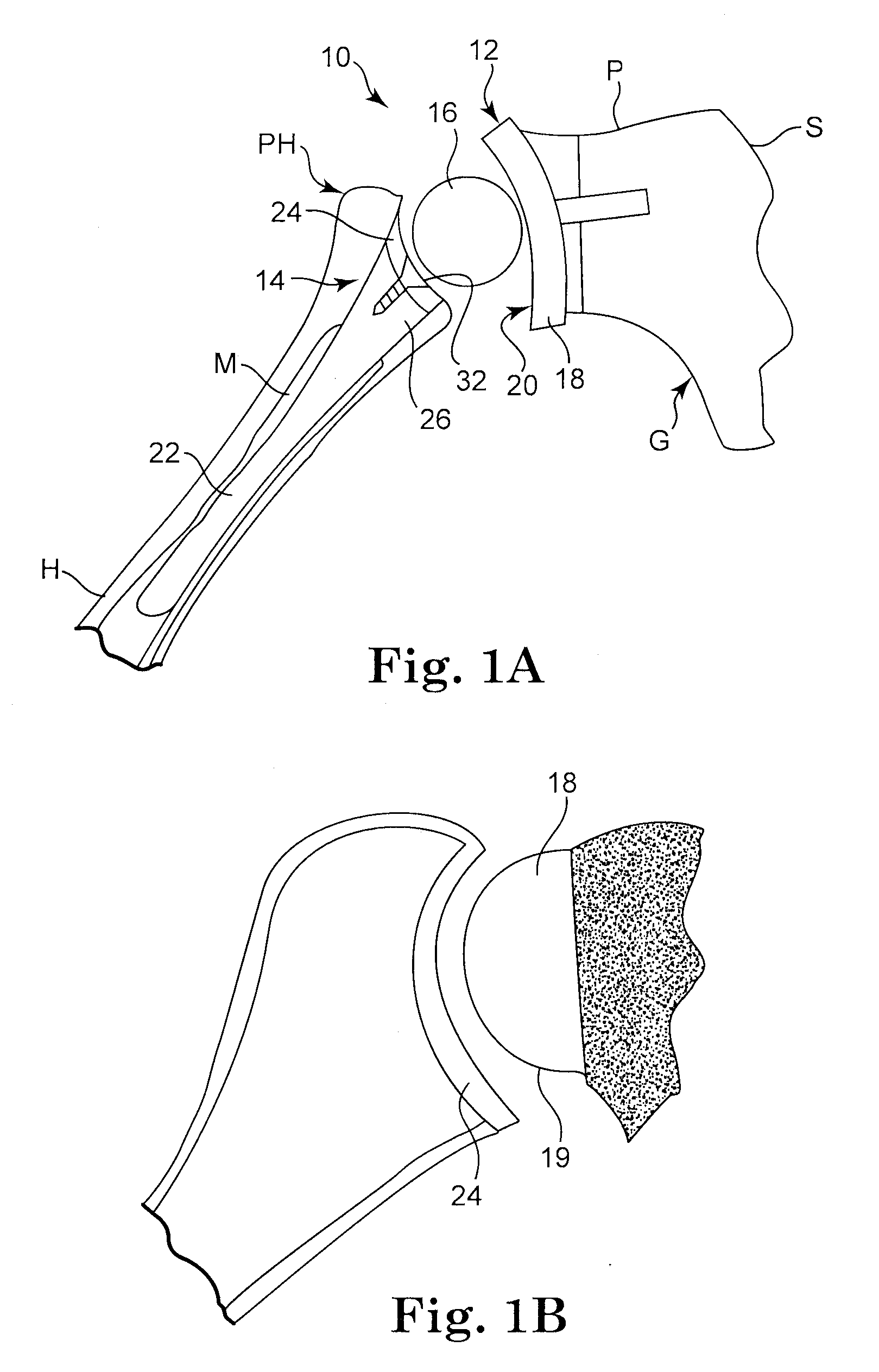
[0019]FIG. 1A shows a schematic view of a prosthesis 10 including a glenoid component 12, a humeral component 14 and an interpositional implant 16. The glenoid component 12 is implanted in the scapula S of the gleonid G. The method and apparatus of the various embodiments of the present invention disclosed herein may be used with a variety of glenoid components, such as for example those disclosed in U.S. Pat. Nos. 7,033,396; 6,953,478; 6,761,740; 6,626,946; 5,702,447 and U.S. Publication Nos. 2004 / 0220673; 2005 / 0278030; 2005 / 0278031; 2005 / 0278032; 2006 / 0020344, which are hereby incorporated by reference. Although the prosthesis 10 is primarily discussed as being implanted in a patient's shoulder, the prosthesis 10 may also be modified and implanted in other locations of a patient's body without departing from the intended scope of the present invention. For example, the prosthesis 10 may be modified to be implanted in a patient's hip, ankle, hands, or feet.

[0020]In the illustrated ...


PUM


Abstract

A method for implanting an intra-articular shoulder prosthesis is provided. The method includes removing a proximal portion of a humerus. The proximal portion of the humerus preferably forms a resected portion. The resected portion has a convex outer surface and an inner surface. The method further includes engaging the convex outer surface of the resected portion with a cut surface of the proximal portion of the humerus. The cut surface of the proximal portion of the humerus and / or the inner surface of the resected portion are optionally processed to form a generally concave surface, such as by impacting. In one embodiment, the inner surface of the resected portion is impacted into engagement with the cut surface of the proximal portion of the humerus. The generally concave inner surface of the resected portion forms a concave articular surface to receive an interpositional implant.

Description

CROSS REFERENCE TO RELATED APPLICATIONS[0001]The present application is a continuation-in-part of U.S. patent application Ser. No. 12 / 020,913 filed Jan. 28, 2008, which claims priority to French application no. 0700622, entitled Méthode et ensemble d'instrumentation chirurgicale pour poser une prothése totale d'épaule inversée, et prothése correspondante, filed Jan. 30, 2007, and also claims the benefit of U.S. Provisional Application Ser. Nos. 60 / 888,437 filed Feb. 6, 2007 and 60 / 971,762 filed Sep. 12, 2007, both entitled Method And Apparatus For Fitting An Inverted Shoulder Prosthesis, and U.S. Provisional Application Ser. No. 61 / 015,042, entitled Intra-Articular Joint Replacement, filed Dec. 19, 2007, the complete disclosures of which are hereby incorporated by reference.TECHNICAL FIELD[0002]The present invention relates to a method and apparatus for implanting a prosthesis at the intersection of two or more bone, and in particular, to a method and apparatus for processing and im...

Claims


Application Information

Patent Timeline
19 Nov 2009
Publication
US20090287309A1
IPC
A61F2/30; A61F5/00; A61F2/40
CPC
A61F2002/4248; A61F2/4014; A61F2220/0041; A61B17/15; A61B17/1682; A61B17/1684; A61B17/1686; A61B17/842
Inventors
WALCH, GILLES; RATRON, YVES-ALAIN