Minimally invasive joint implant with 3-dimensional geometry matching the articular surfaces

a minimally invasive, joint technology, applied in the field of orthopedic implants and systems, can solve the problems of serious physical deformity and debilitation, limited repair ability of cartilage, loss of underlying tissue and bone, etc., and achieve the effect of facilitating the integration of a wide variety of cartilage and bone repair materials and enhancing the success of repair

Active Publication Date: 2010-09-21
CONFORMIS
View PDF362 Cites 286 Cited by
  • Summary
  • Abstract
  • Description
  • Claims
  • Application Information

AI Technical Summary

Benefits of technology

[0011]The present invention provides methods and compositions for repairing joints, particularly devices and implants useful for repairing articular cartilage and for facilitating the integration of a wide variety of cartilage and bone repair materials into a subject. Among other things, the techniques described herein allow for the production of devices that substantially or completely conform to the contour of a particular subject's u...

Problems solved by technology

Adult cartilage has a limited ability of repair; thus, damage to cartilage produced by disease, such as rheumatoid arthritis and/or osteoarthritis, or trauma can lead to serious physical deformity and debilitation.
Implantation of these prosthetic devices is usually associated with loss of underlying tissue and bone without recovery of the full function allowed by the original cartilage and, with some devices, serious long-term complications associated with the loss of significant amount of tissue and bone can include infection, osteolysis and also loosening of the implant.
As can be appreciated, joint arthroplasties are highly invasive and require surgical resection of the entire, or a majority of the, articular surface of one or more bones involved in the repair.
Reaming results in a loss of the patient's bone stock and over time osteolysis will frequently lead to loosening of the prosthesis.
Further, the area where the implant and the bone mate degrades over time requiring the prosthesis to eventually be replaced.
Since the patient's bone stock is limi...

Method used


Image

  • Minimally invasive joint implant with 3-dimensional geometry matching the articular surfaces
  • Minimally invasive joint implant with 3-dimensional geometry matching the articular surfaces
  • Minimally invasive joint implant with 3-dimensional geometry matching the articular surfaces

Examples


Embodiment Construction

[0075]The following description is presented to enable any person skilled in the art to make and use the invention. Various modifications to the embodiments described will be readily apparent to those skilled in the art, and the generic principles defined herein can be applied to other embodiments and applications without departing from the spirit and scope of the present invention as defined by the appended claims. Thus, the present invention is not intended to be limited to the embodiments shown, but is to be accorded the widest scope consistent with the principles and features disclosed herein. To the extent necessary to achieve a complete understanding of the invention disclosed, the specification and drawings of all issued patents, patent publications, and patent applications cited in this application are incorporated herein by reference.

[0076]As will be appreciated by those of skill in the art, the practice of the present invention employs, unless otherwise indicated, conventi...


PUM

PropertyMeasurementUnit
Lengthaaaaaaaaaa
Lengthaaaaaaaaaa
Fractionaaaaaaaaaa

Abstract

This invention is directed to orthopedic implants and systems. The invention also relates to methods of implant design, manufacture, modeling and implantation as well as to surgical tools and kits used therewith. The implants are designed by analyzing the articular surface to be corrected and creating a device with an anatomic or near anatomic fit; or selecting a pre-designed implant having characteristics that give the implant the best fit to the existing defect.

Description

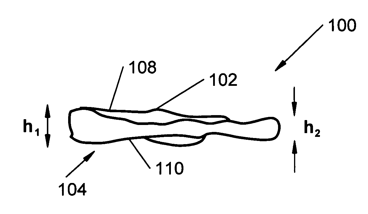
CROSS-REFERENCE TO RELATED APPLICATIONS[0001]This application claims priority to U.S. Provisional Patent Application 60 / 416,601 filed by Philipp Lang on Oct. 7, 2002 for “Minimally Invasive Joint Implant with 3-Dimensional Geometry Matching the Articular Surfaces” and U.S. Provisional Patent Application 60 / 467,686 filed by Philipp Lang, Daniel Steines, Hacene Bouadi, David Miller, Barry J. Linder, and Cecily Anne Snyder for “Joint Implants” on May 2, 2003.FIELD OF THE INVENTION[0002]This invention is directed to orthopedic implants and systems. The implants can be joint implants and / or interpositional joint implants. The invention also relates to methods of implant design, manufacture, modeling and implantation as well as to surgical tools and kits used therewith. This invention also relates to a self-expandable orthopedic implant amendable to arthroscopic insertion and profile alteration. Finally, this invention is related to joint implants that are shaped such that the implants re...

Claims


Application Information

Patent Timeline
IPC IPC(8): A61F2/38A61B17/00A61F2/00A61F2/02A61F2/30A61F2/32A61F2/34A61F2/36A61F2/40A61F2/42A61F2/46
CPCA61F2/30756A61F2/30942A61F2/32A61F2/3603A61F2/38A61F2/3804A61F2/40A61F2/42A61F2/4202A61F2/4261A61F2/4657A61B17/00234A61F2/30767A61F2/34A61F2/4081A61F2/4603A61F2002/30016A61F2002/30062A61F2002/3007A61F2002/30092A61F2002/30113A61F2002/30125A61F2002/30133A61F2002/30179A61F2002/30242A61F2002/30247A61F2002/30253A61F2002/30324A61F2002/30604A61F2002/30616A61F2002/30822A61F2002/30841A61F2002/30843A61F2002/30878A61F2002/30884A61F2002/30892A61F2002/30894A61F2002/30948A61F2002/30952A61F2002/30957A61F2002/30962A61F2002/3208A61F2002/3216A61F2002/3412A61F2002/3414A61F2002/4007A61F2002/4233A61F2002/4251A61F2002/4631A61F2002/4635A61F2210/0004A61F2210/0014A61F2230/0006A61F2230/0008A61F2230/0015A61F2230/0058A61F2230/0071A61F2230/0076A61F2250/0019A61F2250/0036A61F2310/00011A61F2310/00179A61F2310/00293A61F2310/00365A61F2310/00383A61F2310/00395A61F2310/00592Y10S264/30Y10T29/49B33Y80/00A61F2002/30245
Inventor LANG, PHILIPPSTEINES, DANIELBOUADI, HACENEMILLER, DAVIDLINDER, BARRY J.SNYDER, CECILY ANNE
Owner CONFORMIS
Why Eureka
Try Eureka