
Image pickup device

Active Publication Date: 2005-03-31
HANGZHOU HIKVISION DIGITAL TECH
View PDF8 Cites 20 Cited by
  • Summary
  • Abstract
  • Description
  • Claims
  • Application Information

AI Technical Summary

Benefits of technology

[0014] For accomplishing the above object, the present inventors have arrived at an image pickup device in which a shield image area for shielding an image of an imaged object on an output image surface is generated based on a control signal transmitted from an external device, the shield image area is synthesized to the image of the object so that the shield image area is prioritized, and in which the so synthesized image is transmitted to the external device in association with the information pertinent to the shield image area.
[0015] More specifically, an image pickup device according to the present invention comprises image pickup means for converting an image of an object into image signals for obtaining the image signals, mask area signal generating means for generating signals of a mask area for masking, on a display image surface, of the image signals obtained by the image pickup means, based on a control signal transmitted from an external device, image signal synthesizing means for synthesizing the mask area signals to the image signals for the object so that the mask area signals are prioritized, and transmission control means for associating the image signals synthesized by the image signal synthesizing means with the information pertinent to the mask area for transmission to the external device.
[0016] With the image pickup device, according to the present invention, a shielding image area for shielding an image of an object on an output image surface is generated based on a control signal transmitted from the external device, the shielding image area is synthesized to the image of the object so that the shielding image area is prioritized over the image of the object, and the so synthesized image is transmitted to the external device in association with the shielding image area. In this manner, the information pertinent to the shielding image area, as changed responsive to the pickup image angle, may be acquired, to avoid the execution of the unneeded image recording operation in dependence upon the controlled pickup image angle.

Problems solved by technology

However, the conventional monitor camera device suffers from a problem that, since the information pertinent to the size of the privacy mask, changed in dependence upon the pickup image angle, cannot be acquired on the side of the image recording device, the image recording operation which is unnecessary to perform on the side of the image recording device, is executed, especially during zoom-up.

Method used


Image

  • Image pickup device
  • Image pickup device
  • Image pickup device

Examples


Embodiment Construction

[0025] Referring now to the drawings, certain preferred embodiments of the present invention are explained in detail.

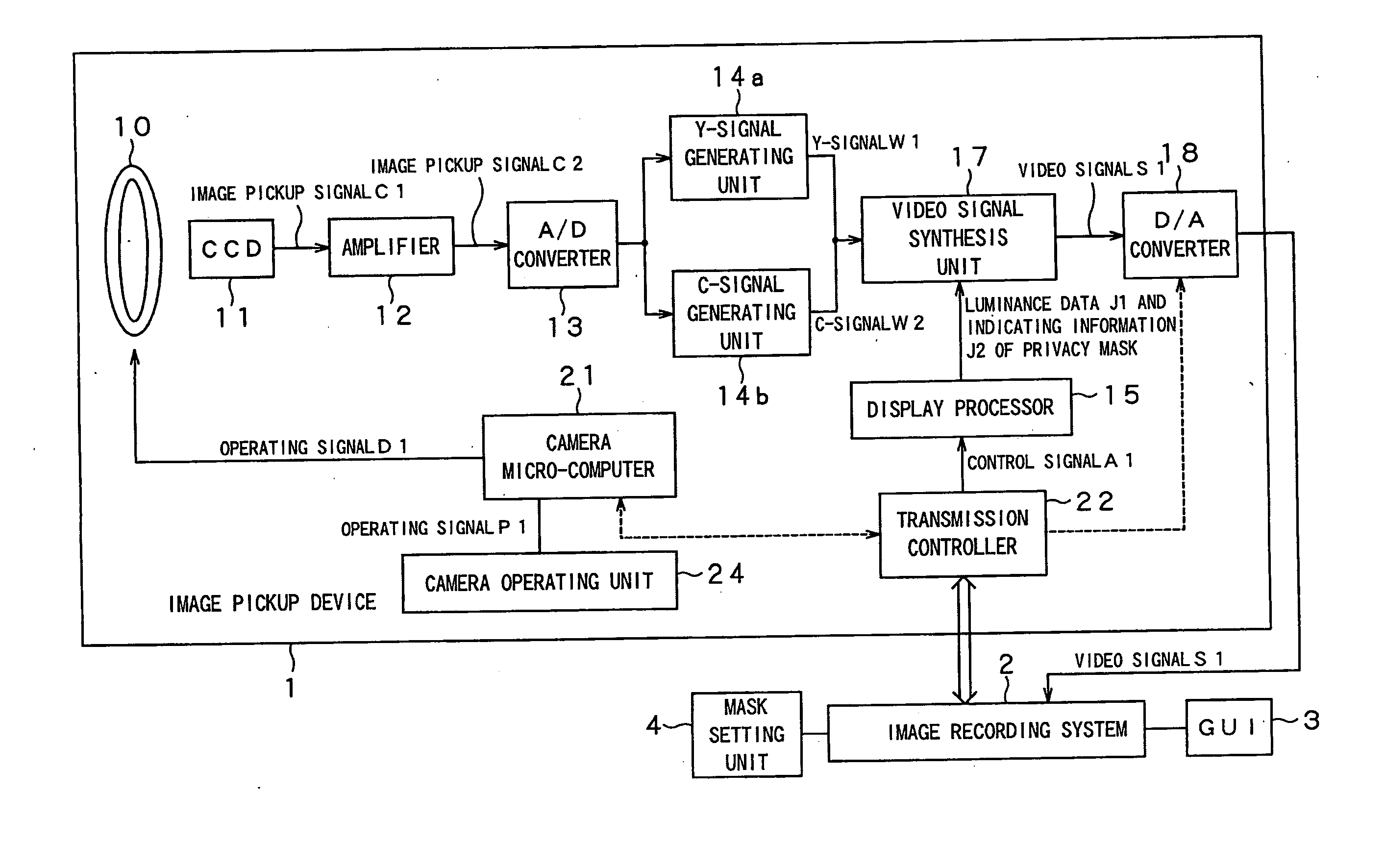
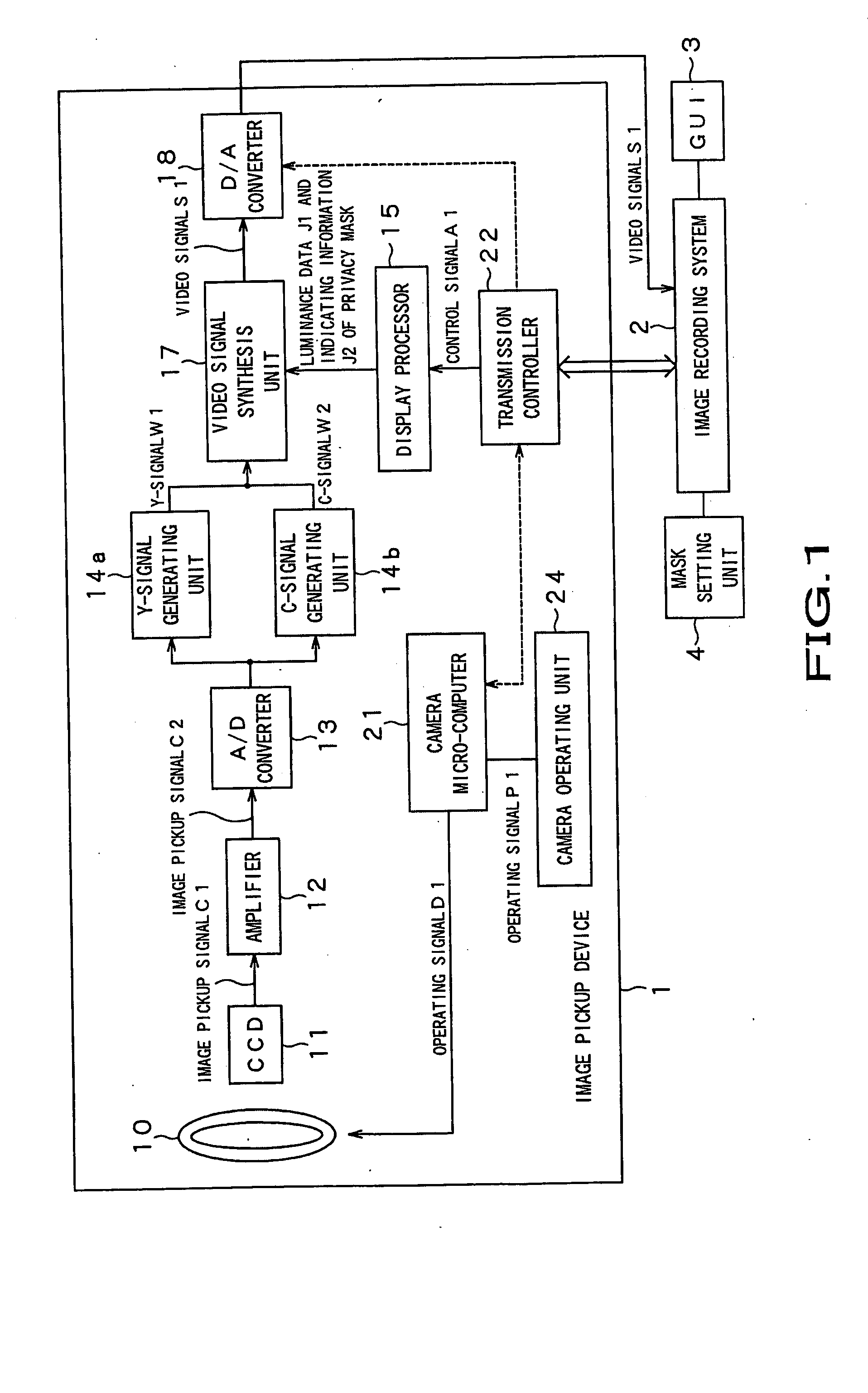
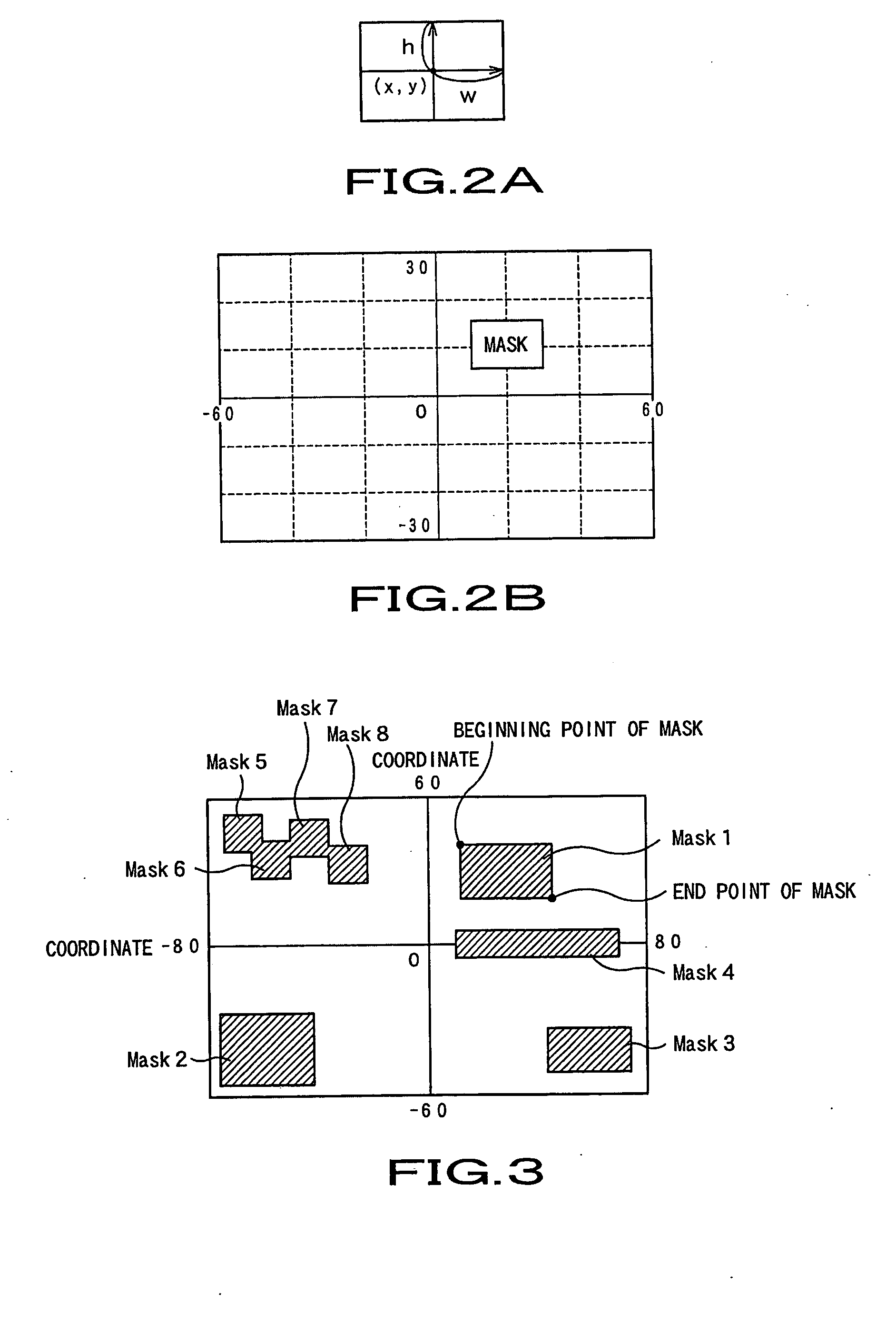
[0026] The present invention is applied to for example an image pickup device 1 shown in FIG. 1. In imaging a subject, the present image pickup device 1 sets a privacy mask, capable of locally screening an output image obtained from image data of a monitor camera, for avoiding simultaneous imaging of a subject possibly infringing the privacy, such as a placard of a company or a window of a residence, referred to below as a private subject.

[0027] The present image pickup device 1 includes an image pickup unit 10 for imaging an object, a CCD (charge-coupled device) 11 for generating image pickup signals Cl based on an object image entered from the image pickup unit 10, an amplifier 12 for amplifying the image pickup signals C1, generated by the CCD 11, and an A / D converter 13 for analog / digital converting image pickup signals C2, supplied from the amplifier 12. The pr...


PUM


Abstract

An image obtained on imaging is correlated with the information pertinent to a privacy mask, designed to shield an image obtained on imaging, for convenience in image recording processing by an external device, including a downstream side image recording device, first and foremost. An image shielding area for shielding the image of an object on an output image surface is generated, based on a control signal transmitted from an image recording system 2. This image shielding area is synthesized to the image of the object so that the image shielding area is prioritized over the image of the object. The synthesized image is correlated with the information pertinent to the image shielding area and sent to the image recording system 2.

Description

BACKGROUND OF THE INVENTION [0001] 1. Field of the Invention [0002] This invention relates to an image pickup device in which a so-called privacy mask is synthesized to an image, obtained on imaging, and the resulting synthesized image is transmitted to an external device. [0003] This application claims priority of Japanese Patent Application No. 2003-338383, filed on Sep. 29, 2003, the entirety of which is incorporated by reference herein. [0004] 2. Description of Related Art [0005] For imaging a news program, or preventing theft or the like acts, a monitor camera is frequently used. The monitor camera, installed on an image pickup site and kept there for a prolonged time, continuously images a subject for imaging, thereby enabling the status of the subject or the progress of the statuses to be observed in realtime. In addition, the image data, obtained on imaging, may be sequentially recorded on a preset recording medium for use for post-analyses. [0006] If, in imaging a subject o...

Claims


Application Information

Patent Timeline
Patent Type & Authority Applications(United States)
IPC IPC(8): H04N5/225G03B17/02G08B13/196G08B15/00H04N5/232H04N5/77
CPCG08B13/19682H04N5/77H04N5/232G08B13/19686H04N23/635
Inventor HAYASAKA, IKUMI
Owner HANGZHOU HIKVISION DIGITAL TECH
Learn More