Shaping die for manufacturing composite material shaped product and method of manufacturing composite material shaped product

Pending Publication Date: 2022-03-24
KAWASAKI HEAVY IND LTD
View PDF1 Cites 0 Cited by
  • Summary
  • Abstract
  • Description
  • Claims
  • Application Information

AI Technical Summary

Benefits of technology

[0018]By the above configuration, the present invention obtains an effect of being able to provide the composite material shaped product manufacturing shaping die which realizes the

Problems solved by technology

However, especially in an aircraft field, high safety and high reliability are required.
In this case, if the releasing treatment with respect to the shaping die is inadequate, the aircraft part as the com

Method used


Image

  • Shaping die for manufacturing composite material shaped product and method of manufacturing composite material shaped product
  • Shaping die for manufacturing composite material shaped product and method of manufacturing composite material shaped product
  • Shaping die for manufacturing composite material shaped product and method of manufacturing composite material shaped product

Examples


Example

Example 1

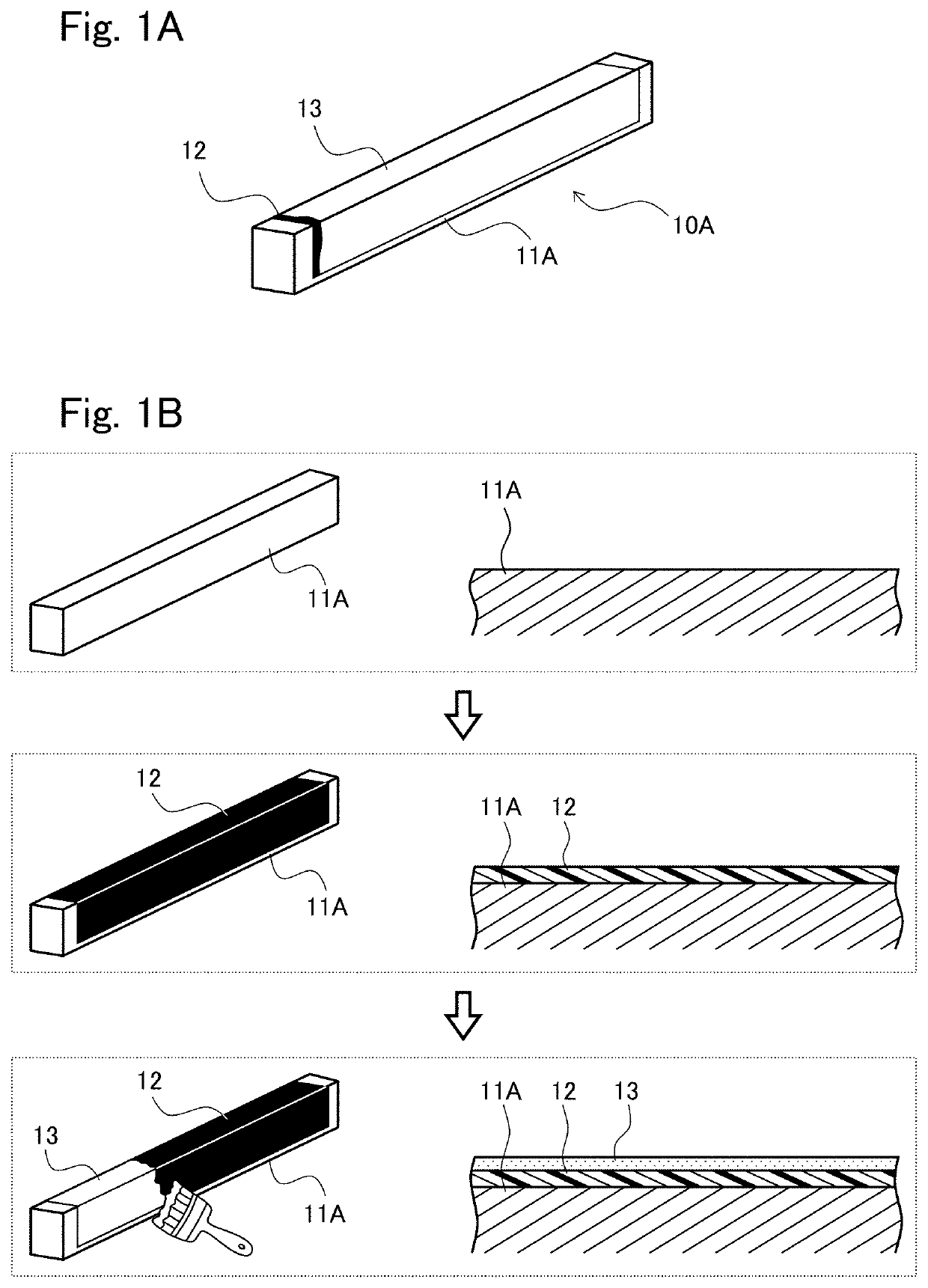
[0073]A commercially available silicone resin release coating was formed on the shaping surface of the beam shaping die (die member), and the release agent layer was formed on the silicone resin coating by applying a commercially available silicone release agent 1 to the silicone resin coating. By using this shaping die, the beams as the composite material shaped products were shaped and removed ten times or more. Each of the formation of the release coating and the application of the release agent layer was performed only once. All the beams were successfully shaped and removed without the reapplication of the release agent layer.

Example

Example 2

[0074]The beams as the composite material shaped products were shaped and removed ten times or more in the same manner as Example 1 except that as the release agent layer, a commercially available silicone release agent 2 was used instead of the silicone release agent 1. Each of the formation of the release coating and the application of the release agent layer was performed only once. All the beams were successfully shaped and removed without the reapplication of the release agent layer.

Example

Comparative Example 1

[0075]The release coating was not formed on the shaping surface of the beam shaping die, but only the release agent layer was formed on the shaping surface of the beam shaping die by applying the silicone release agent 1 to the shaping surface of the beam shaping die. By using this shaping die, the beams as the composite material shaped products were shaped and removed about three to five times, and after that, the successful removing could not be performed any more. Moreover, when the removing was repeatedly performed while applying the release agent layer each time the removing was performed, the release agent layer deposited on the shaping surface was transferred to the surface of the beam. Therefore, the surface roughness of the beam deteriorates. In addition, in nondestructive inspection, ultrasonic transmission was not successfully performed, and the release agent needed to be removed by sanding.


PUM

PropertyMeasurementUnit
Coloraaaaaaaaaa
Shapeaaaaaaaaaa
Affinityaaaaaaaaaa

Abstract

A composite material shaped product manufacturing shaping die is used when manufacturing a composite material shaped product constituted by at least a resin composition and a fiber material. The composite material shaped product is formed by shaping, by the shaping die, a laminated body of prepregs each formed by impregnating the fiber material with the resin composition. The shaping die includes a die member having a shaping surface defining an outer surface shape of the laminated body. The shaping surface of the die member includes: a release coating covering the shaping surface; and a release agent layer formed on the release coating by applying a release agent to the release coating.

Description

TECHNICAL FIELD[0001]The present invention relates to a shaping die used to manufacture a composite material shaped product and a method of manufacturing the composite material shaped product, and particularly to a shaping die for a composite material shaped product and a method of manufacturing the composite material shaped product each of which can realize an excellent release property and excellent surface quality of the obtained composite material shaped product.BACKGROUND ART[0002]In recent years, fiber-reinforced resin composite materials (hereinafter suitably abbreviated as “composite materials”) are widely used in fields in which metal materials have been used. For example, a carbon-fiber reinforced material (carbon fiber reinforced plastic; CFRP) is smaller in weight and higher in strength than the metal material, the carbon-fiber reinforced material being formed in such a manner that: carbon fiber is used as reinforced fiber; and the carbon fiber is impregnated with matrix...

Claims


Application Information

Patent Timeline
IPC IPC(8): B29C33/64B29C33/58B29C70/30B29C70/54
CPCB29C33/64B29C70/54B29C70/30B29C33/58
Inventor SANA, TOSHIKAZUOGASAWARA, SHODO
Owner KAWASAKI HEAVY IND LTD
Why Eureka
Try Eureka