
Reactor internal structure and method of manufacturing the same

Inactive Publication Date: 2011-10-20
KK TOSHIBA
View PDF4 Cites 0 Cited by
  • Summary
  • Abstract
  • Description
  • Claims
  • Application Information

AI Technical Summary

Benefits of technology

[0012]The present invention has been conceived to solve the defective matters described above, and an object of the present invention is to provide a reactor internal structure that can sufficiently suppress deposition of crud on a reactor internal structure of a boiling water reactor.
[0013]Another object of the present invention is to provide a method of inexpensively manufacturing a reactor internal structure that can sufficiently suppress deposition of crud with a simple manufacturing process and is applicable to a complexly shaped member or a large-sized member.
[0014]The inventors of the present invention have earnestly studied suppression of deposition of crud on a reactor internal structure of a boiling water reactor, and as a result, the inventors found that deposition of crud can be suppressed by forming a coating of niobium oxide, zirconium titanate, or nickel titanate and also found that a high-quality coating of niobium oxide, zirconium titanate, or nickel titanate can be inexpensively formed by so-called chemical solution deposition including the steps of: applying a solution containing a compound of these metals to the surface of the reactor internal structure; and forming a coating by heat-treating the reactor internal structure coated with these solutions. Thus, the present invention has been completed.
[0019]According to the present invention, it is possible to suppress deposition and buildup of crud on a surface of the member of the reactor internal structure constituting the boiling water reactor, thereby keeping initial performance of coolant passing through the reactor. Moreover, according to the manufacturing method of the present invention, the reactor internal structure capable of sufficiently suppressing deposition of crud can be manufactured with a simple manufacturing process at low manufacturing cost.

Problems solved by technology

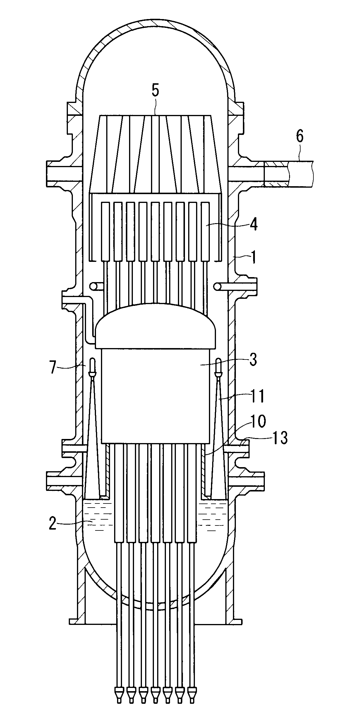
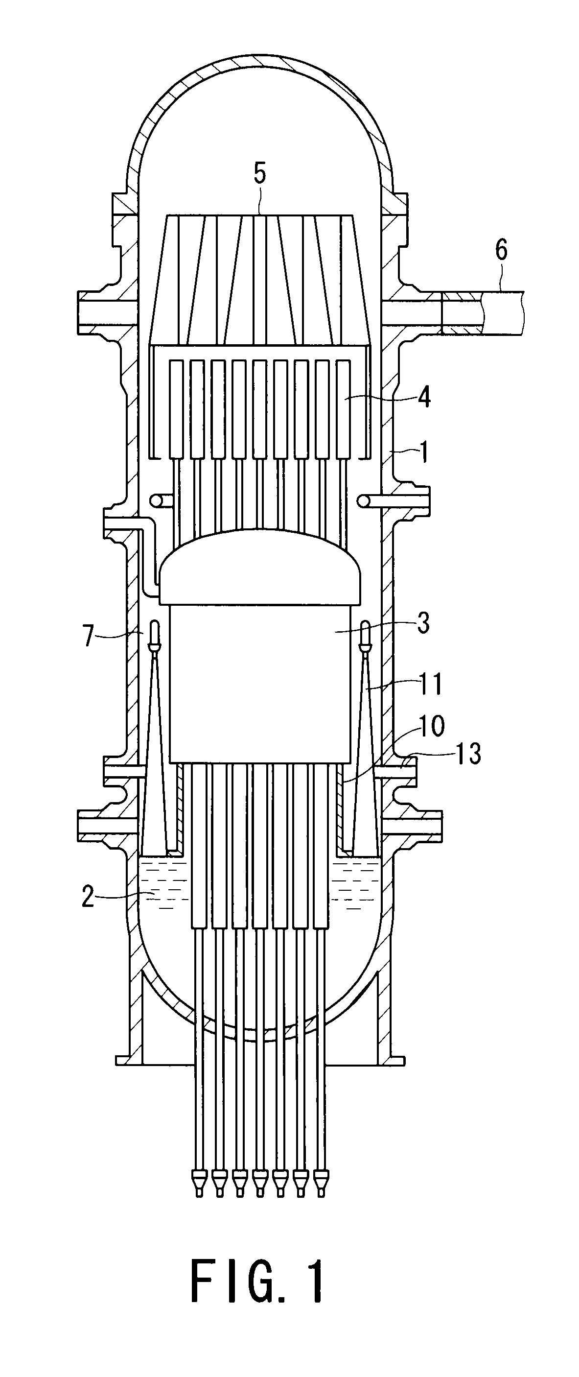
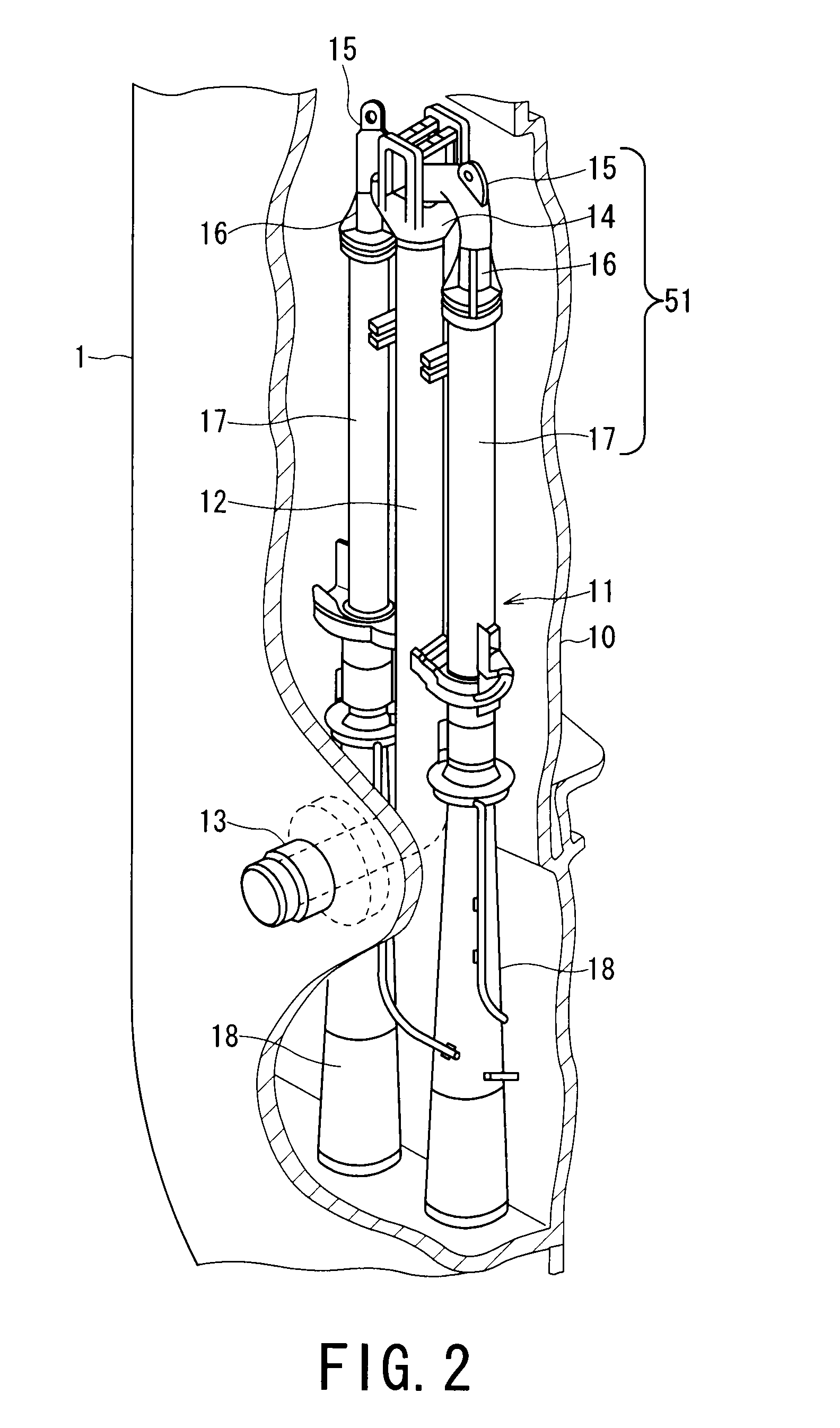
In the case of jet pumps constituting a boiling water reactor, unfortunately, crud of iron oxide in the reactor water is deposited and builds up on surfaces of jet pump members constituting the jet pump, which increases a pressure loss and reduces a flow rate, resulting in lower circulation efficiency.
The components of the reactor internal structure provides like or similar problem.
This matter has been dealt with at present by increasing the speeds of recirculating pumps (PLR pumps), which however has caused a large energy loss.
Further, although a water jet cleaning method has been also proposed to remove the deposited crud, this involves extremely high cost, thus being not practical.
As mentioned above, in reactor internal structures such as jet pumps of a boiling water reactor, the crud in reactor water is deposited and builds up on, e.g., surfaces of jet pump members constituting the reactor internal structures, which might increase a pressure loss and a flow rate, resulting in lower circulation efficiency.
In these proposals, however, deposition of crud cannot be sufficiently suppressed by forming the coatings.
Moreover, the formation of the coatings requires an expensive apparatus, and size and shape of members to be coated are limited.

Method used


Image

  • Reactor internal structure and method of manufacturing the same
  • Reactor internal structure and method of manufacturing the same
  • Reactor internal structure and method of manufacturing the same

Examples


first example

[0041]As a test piece, there was prepared SUS304L stainless steel worked into a rectangular test piece of 40 mm×5 mm×1 mm.

[0042]A 5-wt % butanol solution of niobium alkoxide was applied to a surface of the test piece by dipping and then the test piece was heat-treated at 400° C. in atmosphere for ten minutes to form a coating. This process was repeated three times to adjust a thickness of the coating.

[0043]The coating formed on the surface of the test piece had a thickness of about 1 μm and contained amorphous niobium oxide.

[0044]A crud deposition characteristic test that was a simulation of an actual nuclear power plant was performed to the test piece having the coating.

[0045]In the crud deposition characteristic test, the test piece is immersed and contained in water at 280° C. and 7 MPa and is kept therein for 300 hours. The water contains crud of 60 ppm which is obtained by mixing hematite (Fe2O3) and magnetite (Fe3O4) in a ratio of 1 to 1. A crud deposition characteristic is ev...

second example

[0047]A coating was formed by the same method under the same conditions as in the first example except for use of an isopropyl alcohol solution containing 5 wt % of titanium-zirconium alkoxide in a one-to-one atomic ratio of titanium to zirconium. The coating formed on a test piece contained amorphous zirconium titanate.

[0048]The test piece having the coating of zirconium titanate underwent a crud deposition characteristic test by the same method as in the first example. As a result, the test piece hardly varied in weight before and after the test.

third example

[0049]A coating was formed by the same method under the same conditions as in the first example except for use of a butanol solution containing 5 wt % of titanium-nickel alkoxide in a one-to-one atomic ratio of titanium to nickel. The coating formed on a test piece contained amorphous nickel titanate.

[0050]The test piece having the coating of nickel titanate underwent a crud deposition characteristic test by the same method as in the first example. As a result, the test piece hardly varied in weight before and after the test.


PUM

PropertyMeasurementUnit
Temperatureaaaaaaaaaa
Thicknessaaaaaaaaaa

Abstract

A coating of niobium oxide, zirconium titanate, or nickel titanate is formed on at least a part of a surface of a jet pump member constituting a jet pump serving as a reactor internal structure of a boiling water reactor. Further, a solution containing, e.g., a niobium compound is applied to at least a part of the surface of the jet pump member constituting the jet pump, and the jet pump member coated with the solution is heat-treated to form a coating of, e.g., niobium oxide. With this configuration, the jet pump member constituting the jet pump of the boiling water reactor is provided such that deposition of crud can be sufficiently suppressed on the jet pump member.

Description

TECHNICAL FIELD[0001]The present invention relates to a reactor internal structure constituting a boiling water reactor and a method of manufacturing the same, and particularly, to a reactor internal structure and a method of manufacturing the same which can suppress deposition of crud on the reactor internal structure.BACKGROUND ART[0002]In a boiling water reactor, a jet pump system is adopted to increase power density. The jet pump system forcibly circulates reactor coolant as cooling water and includes an external recirculating system and an internal recirculating system as systems for forcibly circulating reactor coolant through a core portion of a reactor pressure vessel.[0003]The external recirculating system includes a plurality of jet pumps in a reactor pressure vessel and a recirculating pump outside the reactor pressure vessel. Cooling water fed from the recirculating pump is jetted by the jet pumps and reactor water around the jet pumps is drawn and forcibly fed into a co...

Claims


Application Information

Patent Timeline
IPC IPC(8): B01J19/00B05D3/02
CPCC23C18/1216C23C18/1241C23C26/00F04F5/10Y02E30/31G21C15/25G21C17/0225G21C19/307F04F5/46Y02E30/30C23C30/005G21C1/084
Inventor SAYANO, AKIOSAITO, NORIHISAKANEKO, TETSUJIMORISHIMA, YASUOOKAMURA, MASATOYAMAZAKI, KENJIKINUGASA, KUNIHIKO
Owner KK TOSHIBA
Learn More