Sliding nozzle

a nozzle and nozzle technology, applied in the field of sliding nozzles, can solve the problems of affecting the quality of steel, the flow pattern and the speed of molten steel discharge, and preventing the discharge of molten steel, so as to suppress the adhesion and deposition of metal oxides, suppress the stagnation of molten steel, and suppress the effect of clogging

Active Publication Date: 2019-11-07
KROSAKI HARIMA CORP +1
View PDF0 Cites 1 Cited by
  • Summary
  • Abstract
  • Description
  • Claims
  • Application Information

AI Technical Summary

Benefits of technology

[0014]The present invention makes it possible to suppress adhesion and deposition of metal oxides and others on the inner bore wall surfaces of the three plates, particularly the intermediate and lower plates, of the sliding nozzle, or suppress clogging of the inner bores of the three plates, particularly the intermediate and lower plates, due to metal oxides and others. Further, the present invention makes it possible to suppress stagnation of molten steel within the inner bore of the intermediate plate.

Problems solved by technology

The progress of adhesion and deposition of metal oxides and others causes clogging of the sliding nozzle, thereby precluding discharge of the molten steel.
Further, a change in flow pattern and a change in molten steel discharge speed are likely to exert an adverse influence on quality of steel.

Method used


Image

  • Sliding nozzle
  • Sliding nozzle
  • Sliding nozzle

Examples


examples

[0041]Experimental examples will be shown and described below. In the following Example A and Example B, with regard to a flow pattern of molten steel, a predominant flow pattern is extracted from knowledge obtained based in simulation and depicted, and, with regard to a state of adhesion and deposition, a typical pattern obtained by observation of a sliding nozzle after being used in actual casting operation is depicted. Further, as a state of the plates depicted in the figures, an open state of the intermediate plate at an approximately constant pouring speed, i.e., at a setup casting speed, is assumed. Further, in the actual casting operation, a refractory member for injecting gas into inner bores was installed to each of the upper nozzle and the upper plate.

example a

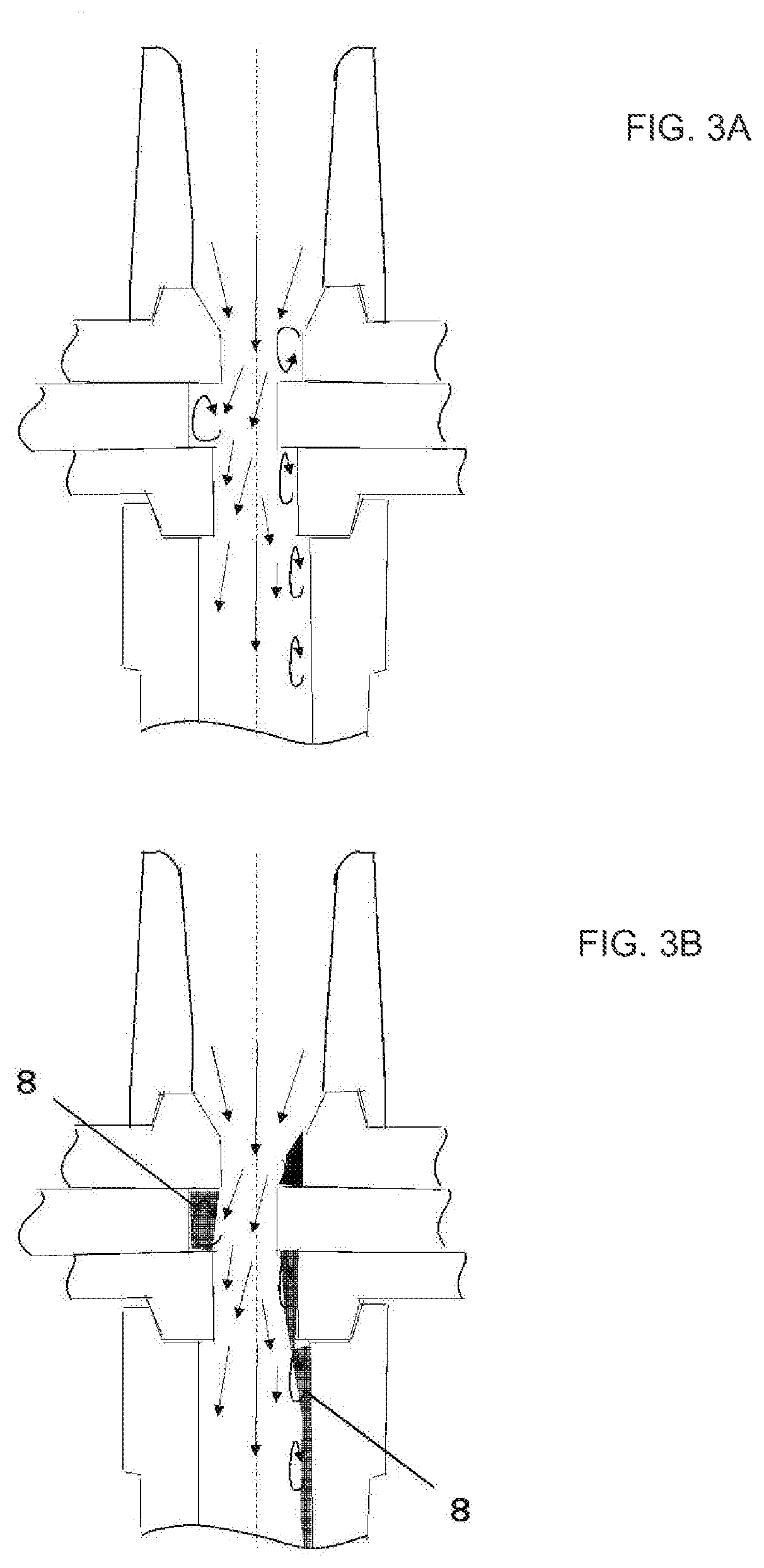
[0042]Example A is an experimental example in which a sliding nozzle configured such that a central axis of an inner bore of an upper plate lies coaxially with a central axis of an inner bore of a lower plate is used to check the flow pattern of molten steel in inner bores and the state of adhesion and deposition of metal oxides and others on inner bore wall surfaces.

[0043]In the actual casting operation, the type of steel was stainless steel containing rare metal such as La and Ce each contained in an amount of 0.1 mass % or less, and the casting speed was 1 t / min or less. These conditions are the same as those in Example B.

[0044]FIG. 3A, FIG. 4A and FIG. 5A are schematic diagrams depicting respective structures of a comparative sample 1 and inventive samples 1 and 2, and FIG. 3B, FIG. 4B and FIG. 5B are schematic diagrams depicting respective states of adhesion and deposition of metal oxides and others on inner bore wall surfaces of these sliding nozzles. FIG. 9 is a graph present...

example b

[0051]Example B is an experimental example in which a sliding nozzle configured such that a central axis of an inner bore of an upper plate lies non-coaxially with a central axis of an inner bore of a lower plate, and the central axis of the inner bore of the lower plate is offset on the slidingly closing directional leading-side with respect to the central axis of the inner bore of the upper plate by 10 mm is used to check the flow pattern of molten steel in inner bores and the state of adhesion and deposition of metal oxides and others on inner bore wall surfaces.

[0052]FIG. 6A, FIG. 7A and FIG. 8A are schematic diagrams depicting respective structures of a comparative sample 2 and inventive samples 3 and 4, and FIG. 6B, FIG. 7B and FIG. 8B are schematic diagrams depicting respective states of adhesion and deposition of metal oxides and others on inner bore wall surfaces of these sliding nozzles. FIG. 9 is a graph presenting a relative relationship of the states of adhesion of meta...


PUM

PropertyMeasurementUnit
diameteraaaaaaaaaa
lengthaaaaaaaaaa
lengthaaaaaaaaaa

Abstract

In a sliding nozzle comprising three plates consisting of an upper plate, an intermediate plate capable of a sliding movement, and a lower plate, it is intended to suppress adhesion and deposition of metal oxides and others on wall surfaces of inner bores of the three plates. The intermediate plate has: a first inclined portion whose surface defines a slidingly closing directional leading-side wall surface of an inner bore thereof and extends obliquely downwardly in a diametrically contracting direction; a second inclined portion whose surface defines an upper part of a slidingly closing directional trailing-side wall surface of the inner bore thereof and extends obliquely downwardly in a diametrically contracting direction, and a third inclined portion whose surface defines a lower part of the slidingly closing directional trailing-side wall surface of the inner bore thereof and extends obliquely downwardly in a diametrically expanding direction.

Description

TECHNICAL FIELD[0001]The present invention relates to a sliding nozzle for controlling the flow rate of molten steel. As used in the present invention, the term “sliding nozzle” means a structure comprising an upper nozzle, an upper plate, an intermediate plate, and a lower plate, wherein the structure is comprised in a sliding nozzle device for adjusting start and stop timings of discharge of molten steel in a molten steel container and the flow rate of the molten steel through an opening-closing operation by a sliding movement of the intermediate plate.BACKGROUND ART[0002]In an operation of discharging molten steel from a ladle to a tundish or from the tundish to a casting mold, a sliding nozzle having a molten steel flow rate control function is installed at the bottom of the ladle or tundish to control the flow rate of the molten steel to be discharged therefrom.[0003]Such molten steel to be discharged contains metal oxides, so that, particularly, during the operation of dischar...

Claims


Application Information

Patent Timeline
Patent Type & Authority Applications(United States)
IPC IPC(8): B22D41/24B22D11/10B22D41/42
CPCB22D11/10B22D41/24B22D41/42B22D41/28B22D41/34B22D41/38
Inventor FUKUNAGA, SHINICHIKAWARADA, KOUJITANI, KOHEIOIKAWA, MASASHI
Owner KROSAKI HARIMA CORP
Why Eureka
Try Eureka