Method and apparatus for manufacturing hot-dip metal plated steel strip

Active Publication Date: 2022-04-26
JFE STEEL CORP
View PDF19 Cites 0 Cited by
  • Summary
  • Abstract
  • Description
  • Claims
  • Application Information

AI Technical Summary

Benefits of technology

The present invention proposes a method and apparatus for manufacturing hot-dip metal plated steel strips that can effectively prevent the adhesion of top dross floating in the region from the exit of support rolls to the surface of the plating bath. The technology uses a flow regulation plate to separate the flow of molten metal from the steel strip, but there is a risk of the top dross adhering to the steel strip. To address this issue, the invention proposes the use of a tapered gap or a mountain-shaped or crescent-shaped gap to efficiently remove dross in the plating bath. The technical effects of the invention include improved quality of the plated steel strips, reduced likelihood of defects, and reduced risk of contamination.

Problems solved by technology

It is, however, difficult for the technology disclosed in Patent Literature 2 to avoid adhesion of the top dross floating in the region from the exit of the support rolls to the bath surface to the steel strip, as in the Patent Literature 1.

Method used


Image

  • Method and apparatus for manufacturing hot-dip metal plated steel strip
  • Method and apparatus for manufacturing hot-dip metal plated steel strip
  • Method and apparatus for manufacturing hot-dip metal plated steel strip

Examples


example 1

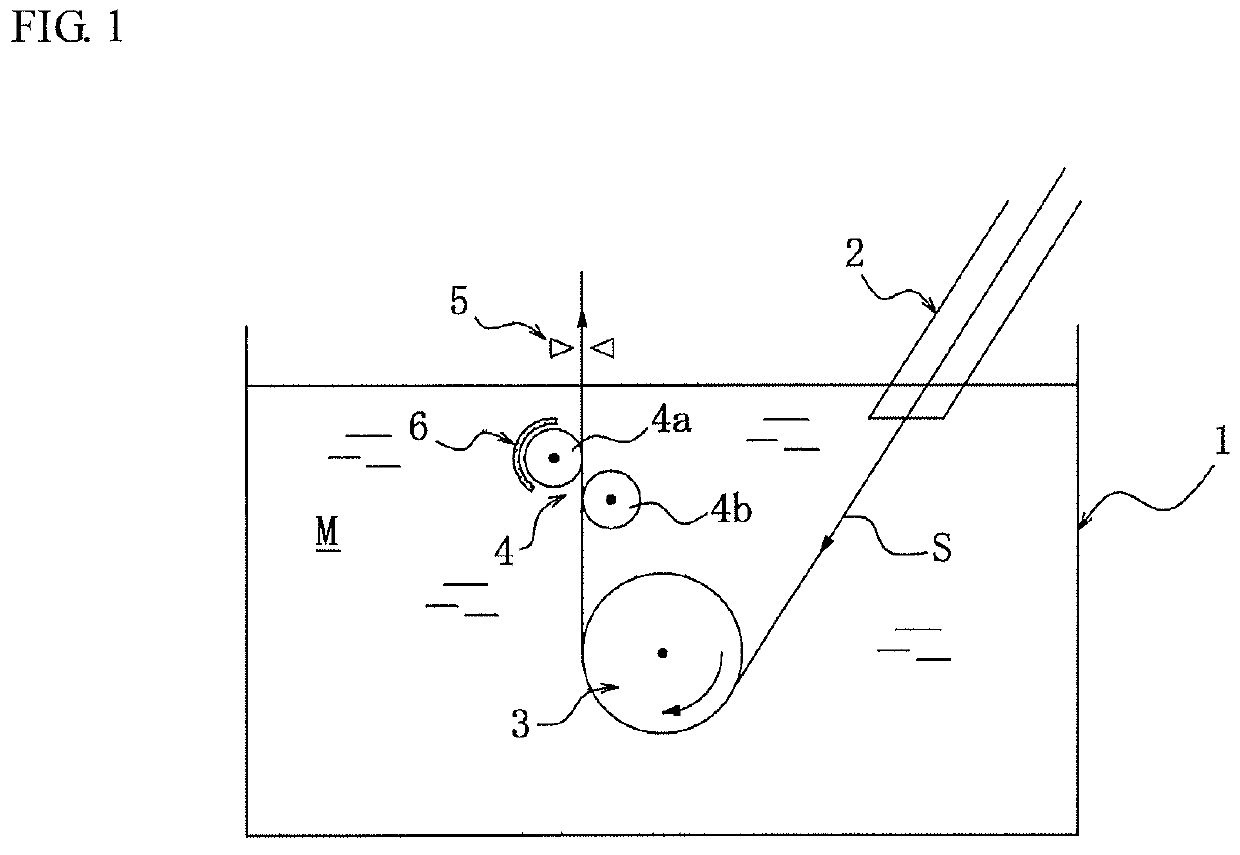
[0038]A cold-rolled steel strip having a width ranging from 800 to 1900 mm and a thickness ranging from 0.4 to 4.0 mm is placed in the manufacturing apparatus shown in FIG. 1 described above, in which a flow regulation plate is disposed in a setting condition shown in Table 1. Hot-dip galvanizing is performed on the cold-rolled steel strip under the following conditions: the bath temperature: 450 to 460° C.; the adhesion amount of plating: 45 to 90 g / m2 per one side; and the linear speed: 60 to 150 mpm, and five sample material plates each having a size of 500 mm by 500 mm are collected from a hot-dip galvanized steel strip (coil) resulting from 300 tons of the processed cold-rolled steel strip. Hat-shape processing (punch diameter: 300 mm ϕ (R: 21 mm), wrinkle preventing pressure: 320 kN, punch speed: 320 mm / min, and product height: 27 mm) is performed on the five collected sample material plates. After the upper surface of each of the five resultant hat-shaped plates is ground wit...

example 2

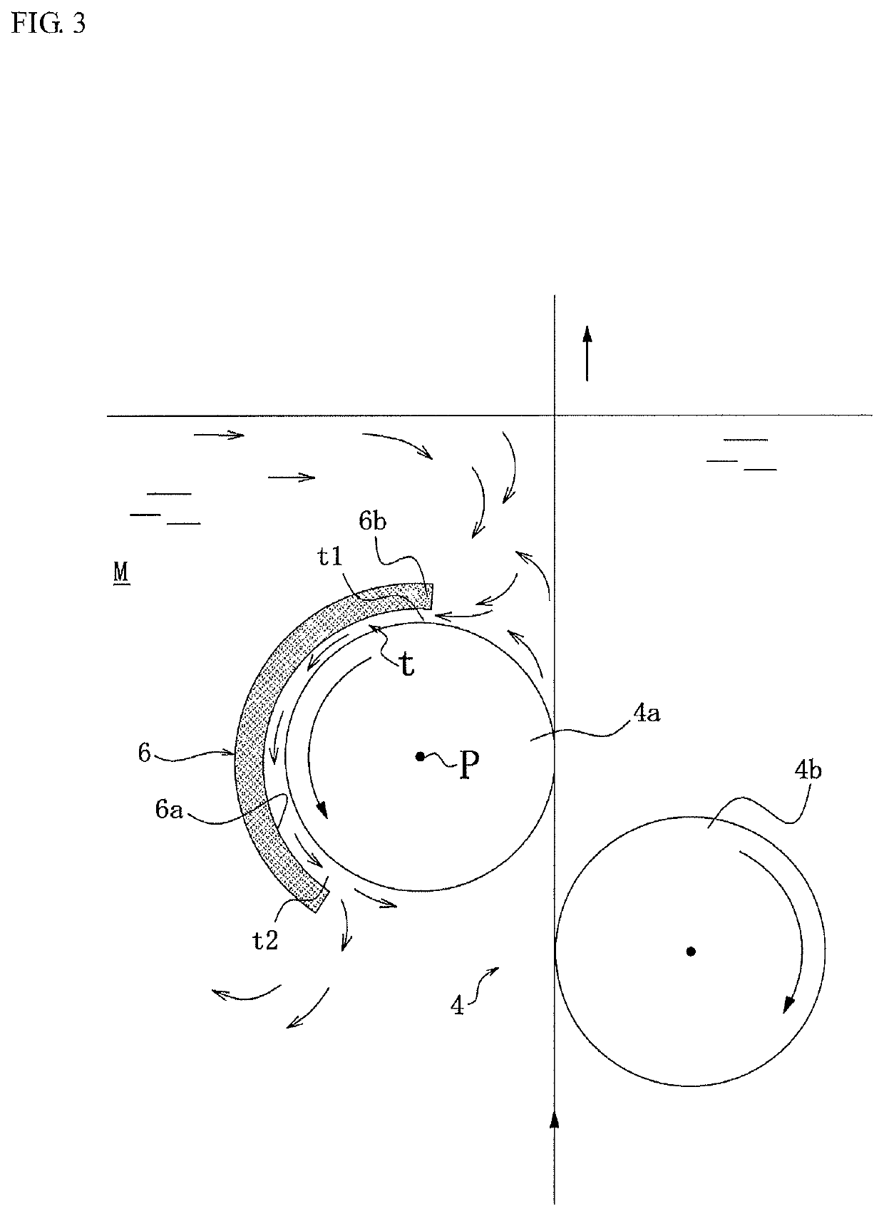
[0041]A manufacturing apparatus having a structure shown in FIG. 3 (upper end of immersed flow regulation plate: 10 mm, angle θ: 90°, and separation distance L: 100 mm) having a tapered gap having the gap dimension continuously increasing from the entrance to the exit of the gap (gap dimension at entrance t1: 10 mm, gap dimension at exit t2: 20 mm) and a manufacturing apparatus having a structure shown in FIG. 4 (upper end of immersed flow regulation plate: 40 mm, angle θ: 135°, and separation distance L: 100 mm) having a crescent-shaped gap having a gap dimension continuously increasing from the entrance to the center of the gap (gap dimension at entrance t1: 10 mm, gap dimension at center t3: 40 mm) and decreasing from the center to the exit of the gap (gap dimension at exit t2: 10 mm) are used to perform hot-dip galvanizing on the same cold-rolled steel strip as in Example 1, and the average number of foreign matter objects resulting from the dross is examined (the plating condit...


PUM

PropertyMeasurementUnit
Dimensionaaaaaaaaaa

Abstract

A method for manufacturing a hot-dip metal plated steel strip having a plated layer formed on the outer surface thereof includes continuously immersing a steel strip in a bath tub that accommodates a molten metal plating bath, causing a sink roll disposed in the bath tub to change the traveling direction of the steel strip, then causing the steel strip to pass through two support rolls formed of a stabilizing roll and a correcting roll disposed above the sink roll but below the surface of the plating bath, and extracting the steel strip out of the bath. A flow regulation plate is disposed so as to cover at least the upper side of a roll body of the stabilizing roll out of the support rolls with a gap between the flow regulation plate and the stabilizing roll, and the flow of the molten metal plating bath directed toward a portion of the steel strip located from the exit of the support rolls to the surface of the plating bath is led toward the lower side of the stabilizing roll via the gap.

Description

CROSS REFERENCE TO RELATED APPLICATIONS[0001]This is the U.S. National Phase application of PCT / JP2018 / 013738, filed Mar. 30, 2018 which claims priority to Japanese Patent Application No. 2017-072883, filed Mar. 31, 2017, the disclosures of each of these applications being incorporated herein by reference in their entireties for all purposes.FIELD OF THE INVENTION[0002]The present invention relates to a method and apparatus for manufacturing a hot-dip metal plated steel strip.BACKGROUND OF THE INVENTION[0003]In a continuous galvanizing in which a hot-dip galvanized steel strip is manufactured by using a hot-dip galvanizing bath as a molten metal plating bath and continuously immersing and passing a steel strip in the plating bath, it is known that foreign matter called dross is produced. As a cause of the production of the dross, it is known that when the steel strip is caused to pass through the hot-dip galvanizing bath, eluted iron flowing out of the steel strip reacts with consti...

Claims


Application Information

Patent Timeline
IPC IPC(8): C23C2/40C23C2/00
CPCC23C2/003C23C2/40C23C2/00344
Inventor KAWABATA, HIRONARIYOSHIMOTO, SOSHIITAGAKI, TAKAHIKO
Owner JFE STEEL CORP
Why Eureka
Try Eureka