

Substrate processing apparatus
- Summary
- Abstract
- Description
- Claims
- Application Information
AI Technical Summary
Benefits of technology
Problems solved by technology
Method used
Image

Examples
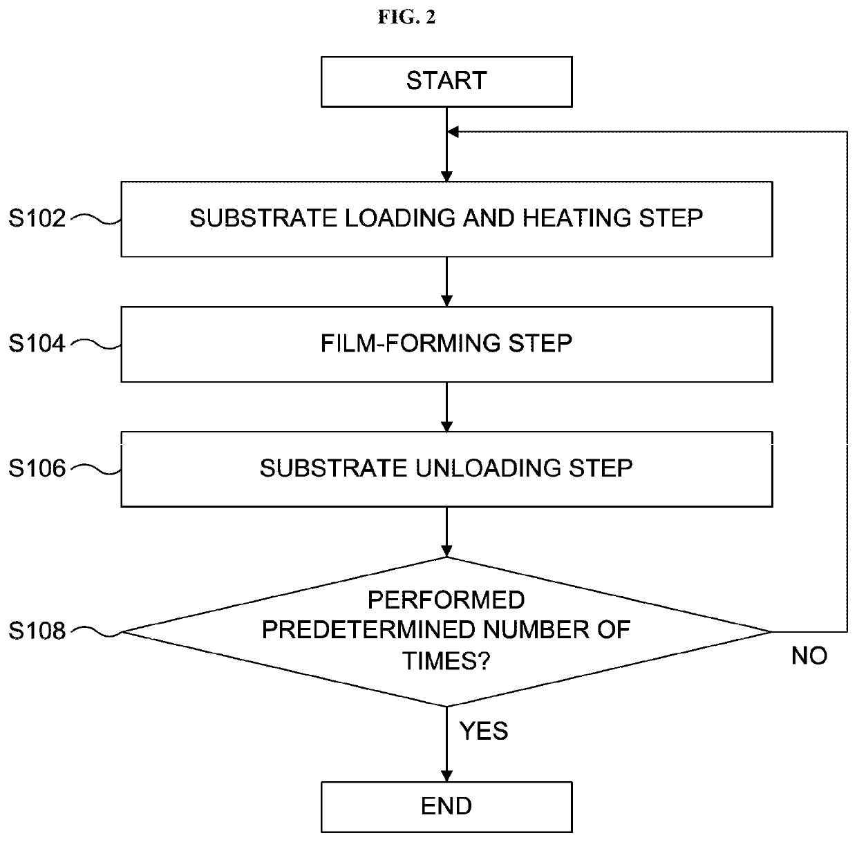
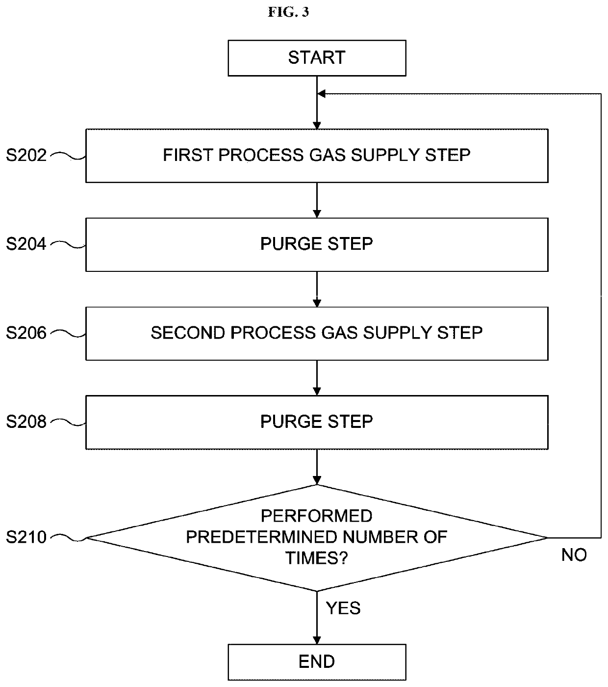
first embodiment
[0014]First, a first embodiment according to the technique of the present disclosure will be described in detail.
[0015](1) Configuration of Substrate Processing Apparatus
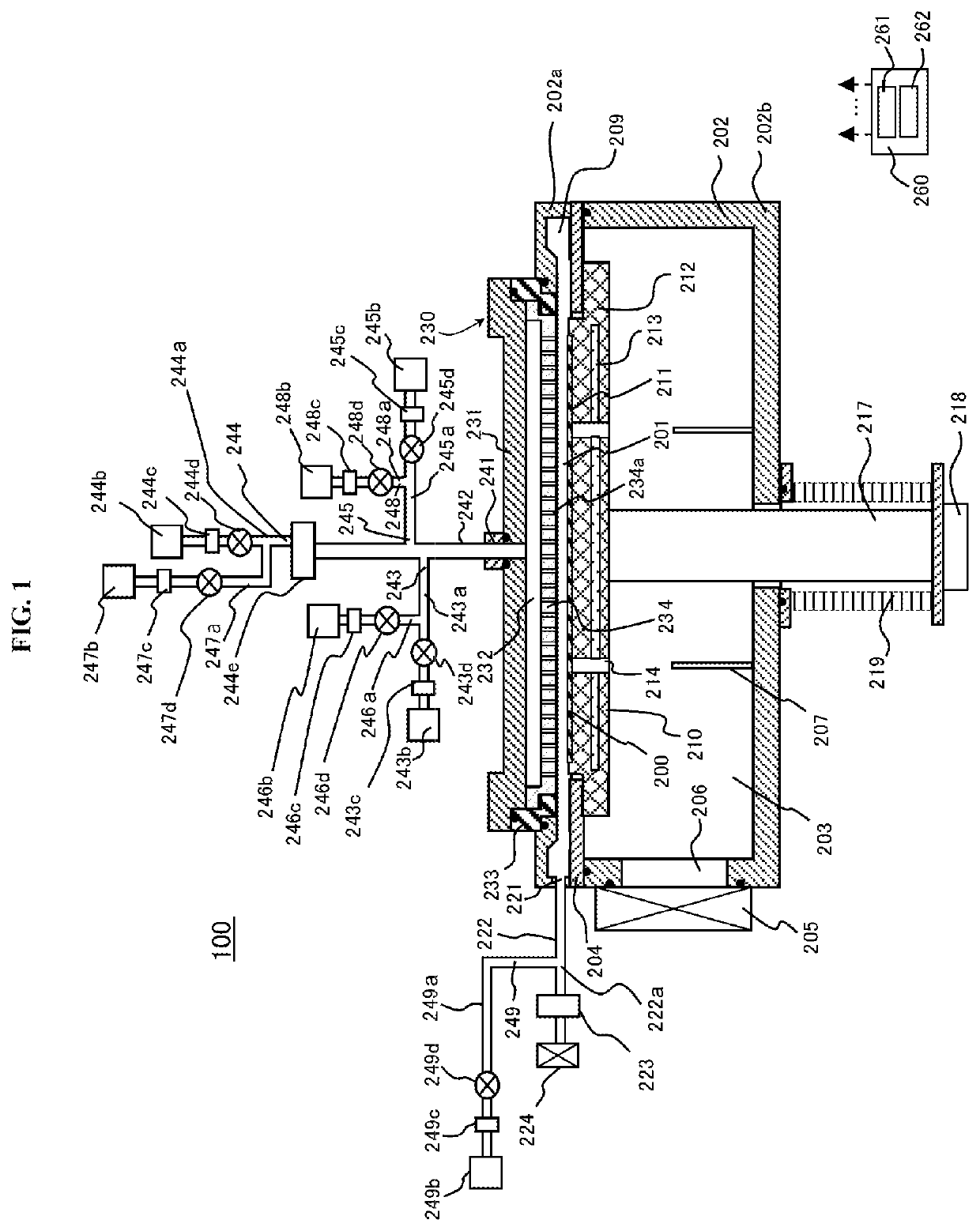
[0016]Hereinafter, a configuration of a substrate processing apparatus according to the first embodiment will be described. The first embodiment will be described by way of an example in which a single-wafer type substrate processing apparatus configured to process a wafer to be processed one by one is used as the substrate processing apparatus according to the first embodiment. FIG. 1 schematically illustrates the single-wafer type substrate processing apparatus according to the first embodiment.
[0017]
[0018]As shown in FIG. 1, a substrate processing apparatus 100 according to the first embodiment includes a process vessel 202. For example, the process vessel 202 is a flat and sealed vessel having a circular horizontal cross-section. The process vessel 202 is made of a metal material such as aluminum (Al) and stainl...
second embodiment
[0123]Hereinafter, a second embodiment according to the technique of the present disclosure will be described in detail. In the second embodiment, only portions different from those of the first embodiment will be described in detail below, and the description of portions the same as the first embodiment will be omitted.
[0124]In the second embodiment, a configuration of the exhaust pipe gas supply system 249 and a cleaning step of the exhaust pipe 222 using the exhaust pipe gas supply system 249 according to the second embodiment are different from those of the first embodiment.
[0125]According to the second embodiment, the cleaning auxiliary gas serving as the cleaning contribution gas is supplied from the exhaust pipe gas supply source 249b of the exhaust pipe gas supply system 249. When the fluorine-containing gas such as NF3 gas and F2 gas is supplied as the cleaning gas into the process chamber 201, an oxygen-containing gas such as nitric oxide (NO) gas and oxygen (O2) gas of ac...
third embodiment
[0136]Hereinafter, a third embodiment according to the technique of the present disclosure will be described. In the third embodiment, only portions different from those of the first embodiment or the second embodiment will be described in detail below, and the description of portions the same as the first embodiment or the second embodiment will be omitted.
[0137]In the third embodiment, a configuration of the exhaust pipe gas supply system 249 and a cleaning step of the exhaust pipe 222 using the exhaust pipe gas supply system 249 are different from those of the first embodiment. FIG. 4 schematically illustrates a single-wafer type substrate processing apparatus (that is, a substrate processing apparatus 100a) according to the third embodiment.
[0138]As shown in FIG. 4, according to the substrate processing apparatus 100a of the third embodiment, the exhaust pipe gas supply system 249 further includes an exhaust pipe gas supply pipe (also referred to as a “third supply pipe”) 249e i...
PUM
 Abstract
Description
Claims
Application Information