Device for improving the visibility conditions in a motor vehicle

a technology for improving the visibility conditions of motor vehicles and vehicles, which is applied in the direction of color television, television systems, transportation and packaging, etc., can solve the problems of vehicle being driven too fast and the risk of overestimation of the field of vision, so as to achieve efficient and safe device operation, consume a large amount of energy, and avoid overestimation.

Inactive Publication Date: 2005-04-07
DAIMLER AG
View PDF9 Cites 3 Cited by
  • Summary
  • Abstract
  • Description
  • Claims
  • Application Information

AI Technical Summary

Benefits of technology

[0026] According to one preferred embodiment of the device, the control unit is embodied in such a way that, in addition to the display, the camera and / or the irradiation source can be switched off. In this context, the camera is switched off with the display or a short time after it. It is thus possible, during operation of the display, for the camera to always be operational and able to supply image data which can be displayed on the display. Alternatively or additionally to the camera, the radiation source is always switched on and off under the control of the control unit. This ensures that very efficient and safe operation of the device is ensured without restricting the operational capability of the device. This also ensures that the camera or the radiation source is not switched off too early, and thus either with the display or directly after it or only much later, since they consume a large amount of energy and can be operated again only very slowly. This has a positive effect on the consumption of energy of the device, which markedly improves the applicability of the device.

Problems solved by technology

As a result of the improved visibility, the vehicle driver can be encouraged to look only at the display and to no longer observe the surroundings directly, which can lead to misinterpretations.
In particular there is the risk of the field of vision being overestimated and the vehicle being driven too fast owing to the assumed better visibility.

Method used


Image

  • Device for improving the visibility conditions in a motor vehicle
  • Device for improving the visibility conditions in a motor vehicle

Examples


Embodiment Construction

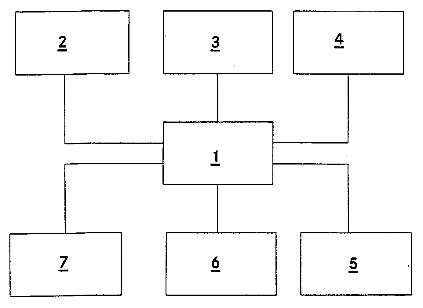
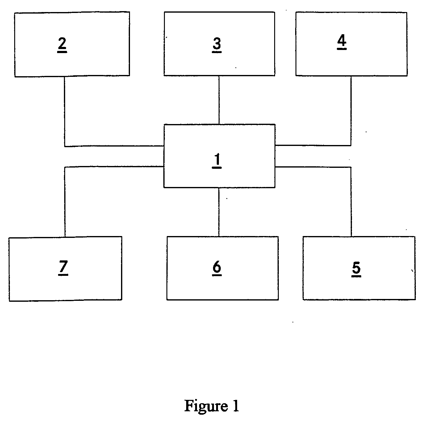
[0029] This device exhibits a radiation source 2 for infrared radiation which irradiates infrared radiation with a wavelength of approximately 800 nm. The radiation source 2 is implemented as an infrared laser. This radiation source 2 is arranged in the front region of the vehicle in the vicinity of the headlights and irradiates the region in front of the vehicle. In addition, this device has an infrared-sensitive camera 3 which is arranged in the vehicle and is orientated in such a way that it senses at least part of the surroundings which are irradiated by the infrared radiation source 2, and feeds the sensed image data to the display 4 via the control unit 1. By means of the display 4, the image data which is fed to it and sensed by the camera 3 is displayed and thus made available to a vehicle driver. The control unit 1 controls the infrared radiation source 2, the camera 3 and the display 4 in this context.

[0030] The infrared radiation source 2 radiates infrared radiation here...


PUM


Abstract

The invention relates to a device for improving the visibility conditions in a motor vehicle, having a radiation source for infrared radiation for irradiating the surroundings of the vehicle, having an infrared-sensitive camera for taking images of at least part of the irradiated surroundings, having a display unit for displaying collected image data, and having a control unit for controlling the device. An image evaluation unit is also provided, which is connected to the camera and the control unit and which evaluates the collected image data with respect to the recommended velocity Vricht and makes it available to a vehicle driver as a velocity recommendation.
In addition the recommended maximum velocity Vmax is optionally evaluated from the image data. A velocity sensor is provided, which is connected to the control unit in such a way that the control unit causes the display to be switched off when the vehicle velocity V exceeds the maximum velocity Vmax. This device ensures that the vehicle with the device operates in a very safe way for the user.

Description

BACKGROUND OF THE INVENTION [0001] 1. Field of Invention [0002] the invention relates to a device for improving the visibility in a motor vehicle. [0003] 2. Related Art of the Invention [0004] DE 40 32 927 C2 discloses a device for improving the visibility in a motor vehicle having a radiation source for infrared radiation for irradiating the surroundings of the vehicle, and having an infrared-sensitive camera which takes images of the irradiated field of vision of the driver and makes available the collected image data to the driver by means of a display device which is embodied as a head-up display and in which the image data is visually superimposed as a visual image on the external landscape. By means of this device, the driver can see considerably better at night or under bad weather conditions, in particular when he is dazzled by oncoming vehicles. As a result of the use of infrared radiation, the driver is, in contrast, not dazzled by the oncoming traffic. Such devices are al...

Claims


Application Information

Patent Timeline
Patent Type & Authority Applications(United States)
IPC IPC(8): B60R1/00H04N5/33H04N7/18
CPCB60R1/00B60R2300/103B60R2300/106B60R2300/301H04N7/18B60R2300/404B60R2300/8053H04N5/33B60R2300/302
Inventor MOISEL, JOERGHOLZ, MICHAEL
Owner DAIMLER AG
Why Eureka
Try Eureka