Device for improving the visibility conditions in a motor vehicle

a technology for improving the visibility conditions of motor vehicles and vehicles, which is applied in the direction of static indicating devices, instruments, television systems, etc., can solve the problems of chronological limitations, achieve simple and safe control of devices, improve visibility, and delay the effect of switching

Inactive Publication Date: 2005-04-07
DAIMLER AG
View PDF9 Cites 16 Cited by
  • Summary
  • Abstract
  • Description
  • Claims
  • Application Information

AI Technical Summary

Benefits of technology

[0020] The representation on the display is preferably switched on again as soon as the vehicle velocity V drops below a predefined velocity limit, which is preferably equal to the recommended maximum velocity Vmax or in the vicinity thereof. This leads to a situation in which the improved visibility is usually available when the velocity is appropriate, whereas it is not available when the velocity is too high—that is to say above the recommended maximum velocity Vmax—in accordance with the control behavior by means of the control unit. This leads to markedly improved road safety.
[0021] It has proven particularly advantageous to develop the device according to the invention in such a way that the display is switched on when the vehicle velocity V drops below the maximum velocity Vmax by the velocity difference V0 in the range of a few kilometers per hour. As a result of this “delayed” switching on of the representation on the display it is possible to implement a switching behavior in the manner of a hysteresis, which can prevent unpleasant switching to and fro or a type of flickering of the display, as a result of the switching off which is controlled by the control unit when the maximum velocity Vmax is exceeded, and the switching on when the vehicle velocity V drops below the maximum velocity Vmax. This can preferably be carried out by selecting the velocity difference V0 in the vicinity of several percent of the recommended maximum velocity Vmax and thus typically in the vicinity of several kilometers per hour, preferably in the vicinity of 5% of the by the evaluated recommended maximum velocity Vmax. A predefined velocity difference V0 in the vicinity of several kilometers per hour ensures very simple and safe control of the device, which can be implemented very easily and cost-effectively. Logically linking the velocity difference V0 to the recommended maximum velocity Vmax ensures dynamic control of the differentiated switching on and switching off process of the display or of the camera in a way which is adapted to a situation, which gives rise to a very pleasant control behavior of the device. Such control which is adapted to the situation proves very pleasant for the vehicle driver, which has a very positive effect on his driving behavior and thus on the road safety.
[0022] Furthermore, it has proven particularly effective to select the control by means of the control unit in such a way that the display is not switched off at the time when the recommended maximum velocity Vmax is exceeded but rather a predefined time period t0 later, that is to say with a delay. This delayed switching off ensures that successive switching off and on does not take place quickly over a short period. Such switching to and fro greatly distracts the vehicle driver and thus decreases traffic safety, just what the invention is intended to prevent. This embodiment of the control unit for switching off the display unit, the radiation source or the camera with a delay by a time period t0 ensures that a pleasant and reliable representation of the surroundings of the vehicle is provided by the device according to the invention in a simple and cost-effective way. In this context, the time period t0 preferably lies in the region of half a minute or a few minutes. This leads to an increase in traffic safety.
[0023] According to another preferred embodiment of the invention, in addition to the on and off switches for the device, an additional switch for switching on the display and / or the camera and / or the radiation source of the device is provided. This additional switch permits active, conscious switching on of the representation of images on the display after the display or the camera has been switched off. This ensures that the vehicle driver can completely activate the device and thus with all the components—in particular the display, the camera and the radiation source—switched off as required by activating the additional switch and can thus obtain the advantage of the improved visibility. It has proven particularly effective here to implement the additional switch in the vicinity of the steering wheel, in particular in the form of a headlamp flasher switch or a rocker on the steering wheel. By arranging the additional switch in the vicinity of the steering wheel it is possible to activate the switch without the driver having to take one or both hands completely off the steering wheel. This leads to very safe handling of the device and thus to an increase in road safety. It has proven particularly effective to use the headlamp flasher switch as an additional switch for the device, ensuring that by actuating the headlamp flasher switch not only the headlamp flasher but also the display or the camera is actuated again. This leads to a situation in which images of at least part of the surroundings of the vehicle which are irradiated by the infrared radiation source are taken by the camera and the collected image data can be displayed on the display.
[0024] According to one preferred embodiment of the device, the control unit is embodied in such a way that, in addition to the display, the camera can be switched off. In this context, the camera is switched off with the display or a short time after it. It is thus possible, during operation of the display, for the camera to always be operational and able to supply image data which can be displayed on the display. Alternatively or in addition to the camera, the radiation source is also switched on and off under the control of the control unit. This ensures that very efficient and safe operation of the device is ensured without restricting the operational capability of the device. This also ensures that the camera or the radiation source is not switched off too early, and thus either with the display or directly after it or only much later, since they consume a large amount of energy and can be operated again only very slowly. This has a positive effect on the consumption of energy of the device, which markedly improves the applicability of the device.
[0025] It has proven particularly effective to embody the device for improving visibility conditions in such a way that the control device is connected to the radiation source for infrared radiation and is suitable for controlling this radiation source in terms of its radiation power and / or the orientation of the radiation as a function of the vehicle velocity V. Here, the radiation source is changed either electronically or on the basis of mechanical, variable settings, in such a way that different regions of the surroundings are irradiated with different radiation powers as appropriate. This embodiment makes it possible to cover the relevant region of the surroundings very effectively and, as a result, reliably sense this effectively irradiated region of the surroundings by means of the camera and make this region available to the vehicle driver, which leads to improved visibility which, in conjunction with the achieved velocity-dependent switching off or even switching on, provides a particularly advantageous and safe device for improving the visibility conditions. In this context, the radiation source is preferably controlled in such a way that, as the velocity of the vehicle increases, the radiation source is directed further into the region in front of the vehicle, or alternatively or additionally the radiation power is increased. It has also proven effective to increase the angle of aperture of the radiation cone of the infrared radiation of the radiation source as the velocity V increases. This leads overall to better illumination, which makes, in particular the evaluation of images in order to determine the maximum vehicle velocity significantly more reliable, thus leading to a better and more pleasant control of the display or of the camera. In addition, the evaluation of images of the camera can be adapted to the directed radiation source, which in turn leads to an improvement in the evaluation quality and to an improvement in the representation on the display.

Problems solved by technology

In this context, the device is controlled in such a way that the representation of the collected image data is not made available to the user at all times but rather only when required, and thus in a chronologically limited fashion.
This state corresponds to the switched-off display since this display is no longer suitable for representing the image data of the collected infrared-irradiated surroundings which are to be represented.

Method used


Image

  • Device for improving the visibility conditions in a motor vehicle
  • Device for improving the visibility conditions in a motor vehicle

Examples


Embodiment Construction

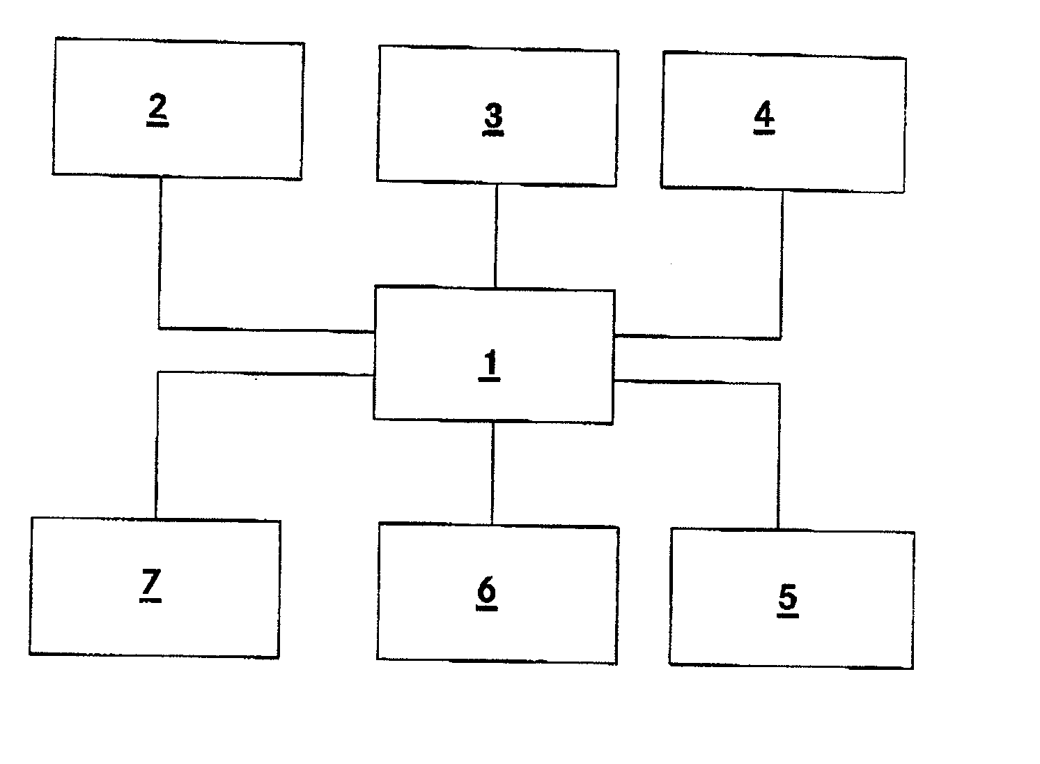
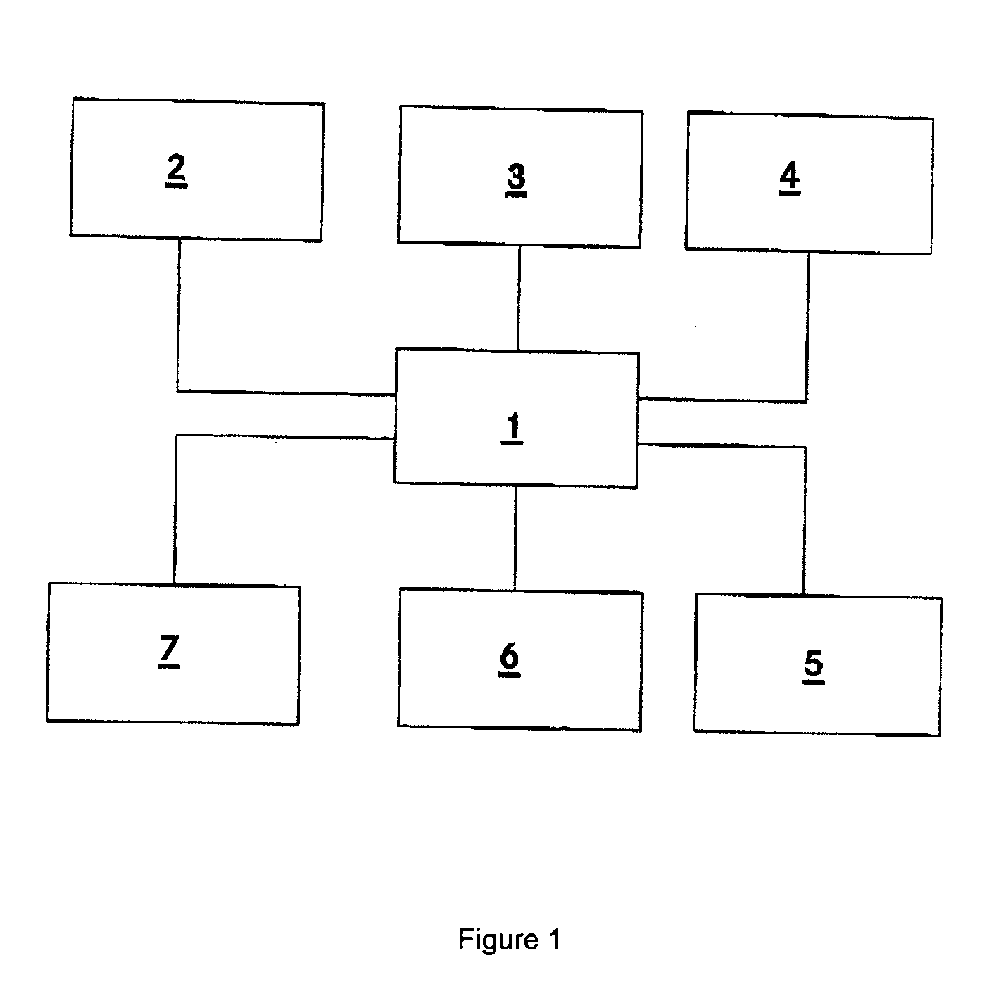
[0028] This device exhibits a radiation source 2 for infrared radiation which irradiates infrared radiation with a wavelength of approximately 800 nm. The radiation source 2 is implemented as an infrared laser. This radiation source 2 is arranged in the front region of the vehicle in the vicinity of the headlights and irradiates the region in front of the vehicle. In addition, this device has an infrared-sensitive camera 3 which is arranged in the vehicle and is orientated in such a way that it senses at least part of the surroundings which are irradiated by the infrared radiation source 2, and feeds the sensed image data to the display 4 via the control unit 1. By means of the display 4, the image data which is fed to it and sensed by the camera 3 is displayed and thus made available to a vehicle driver. The control unit 1 controls the infrared radiation source 2, the camera 3 and the display 4 in this context.

[0029] The infrared radiation source 2 radiates infrared radiation here...


PUM


Abstract

The invention relates to a device for improving the visibility conditions in a motor vehicle, having a radiation source for infrared radiation for irradiating the surroundings of the vehicle, having an infrared-sensitive camera for taking images of at least part of the irradiated surroundings, having a display unit for displaying collected image data, and having a control unit for controlling the device. In this context, the control unit is embodied in such a way that, while the device is operating, the display represents image data in a chronologically limited fashion by means of controlled switching on and switching off, and in the process the switching off of the representation of images on the display is made gradual. The gradual switching off is carried out in particular by changing the brightness limiting values, the contrast limiting values and/or by increasing or reducing the noise of the image data to be represented. Furthermore, the gradual switching off preferably has a time-dependent or velocity-dependent profile. This device ensures that the vehicle with the device operates in a very safe way for the user.

Description

BACKGROUND OF THE INVENTION [0001] 1. Field of Invention [0002] The invention relates to a device for improving the visibility in a motor vehicle. [0003] 2. Related Art of the Invention [0004] DE 40 32 927 C2 discloses a device for improving the visibility in a motor vehicle having a radiation source for infrared radiation for irradiating the surroundings of the vehicle, and having an infrared-sensitive camera which takes images of the irradiated field of vision of the driver and makes available the collected image data to the driver by means of a display device which is embodied as a head-up display and in which the image data is visually superimposed as a visual image on the external landscape. By means of this device, the driver can see considerably better at night or under bad weather conditions, in particular when he is dazzled by oncoming vehicles. As a result of the use of infrared radiation, the driver is, in contrast, not dazzled by the oncoming traffic. Such devices are al...

Claims


Application Information

Patent Timeline
Patent Type & Authority Applications(United States)
IPC IPC(8): B60R1/00G08G1/16B60R11/02H04N7/18
CPCB60R1/00B60R2300/103B60R2300/106H04N7/183B60R2300/404B60R2300/8053B60R2300/302H04N7/18
Inventor MOISEL, JOERGHOLZ, MICHAEL
Owner DAIMLER AG
Why Eureka
Try Eureka