Line voltage compensation system for power chair

Active Publication Date: 2005-04-14
MIDMARK
View PDF21 Cites 11 Cited by
  • Summary
  • Abstract
  • Description
  • Claims
  • Application Information

AI Technical Summary

Benefits of technology

[0013] By virtue of the foregoing there is provided an improved chair positioning system that addresses shortcomings of the prior art. Thes

Problems solved by technology

This inconsistency is often attributable to variance in the line voltage supplied to the chair.
Consequently, the speed at which the chair moves reflects this variance, and the chair often fails to move at the target speed.
This variance and unpredictability poses an inconvenience and distraction to healthcare professionals and patients, alike.

Method used


Image

  • Line voltage compensation system for power chair
  • Line voltage compensation system for power chair
  • Line voltage compensation system for power chair

Examples


Embodiment Construction

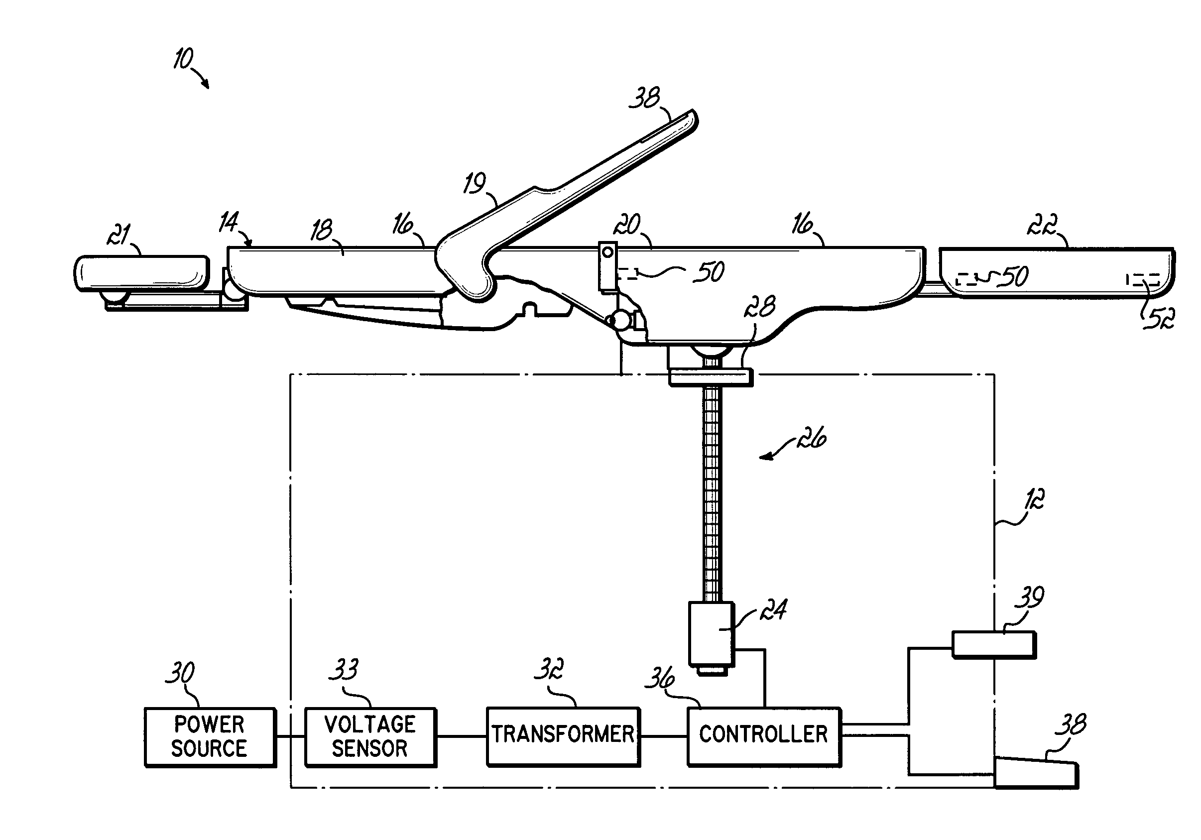
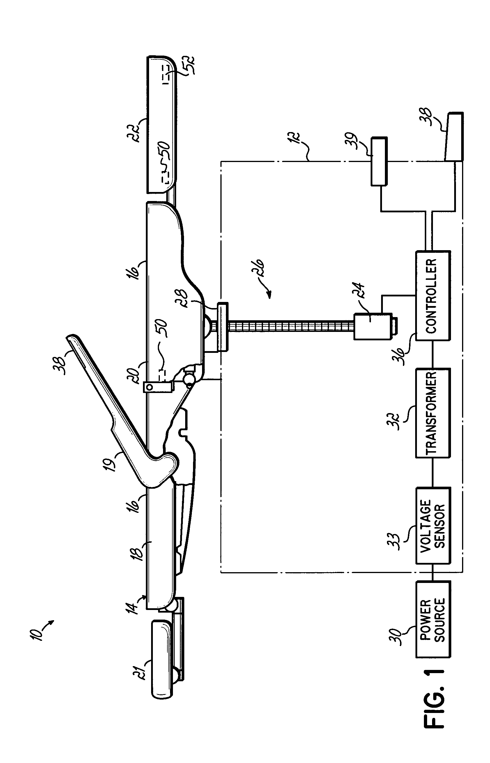
[0019]FIG. 1 shows chair system 10 that may be positioned at a desired speed in accordance with the principles of the present invention. The chair system 10 includes a moveable column 12 to which a support surface 14 is mounted. Upholstered sections 16 are removable and mounted to the support surface 14. As shown in FIG. 1, the support surface 14 comprises a back support 18 and a head support 21 that pivotally attach to a seat support 20. The support surface 14 additionally includes a foot support 22, which also pivotally attaches to the seat support 20. The chair system 10 illustrated in FIG. 1 is equipped with powered tilt and elevation and may be positioned in a number of ways.

[0020] The block diagram of FIG. 1 shows a motor 24 configured to power an actuator 26. A motor 24 comprises a direct current (DC) motor. One skilled in the art, however, will appreciate that any manner of electric motor, including alternating current (AC) motors, may be alternatively used in accordance wi...


PUM


Abstract

An apparatus, method and program product position a powered examination chair at a constant, desired speed despite fluctuations line voltage. A power signal supplied to an actuating motor of the chair is apportioned according to the line voltage supplied to the chair. The desired speed may be customized by a user in the field.

Description

CROSS-REFERENCE TO RELATED APPLICATION [0001] This application is related to concurrently filed U.S. patent applications entitled “Load Compensation System for Power Chair” and “Smooth Start System for Power Chair.” The entire disclosures of these U.S. patent applications are incorporated into this application by reference.FIELD OF THE INVENTION [0002] The present invention relates to powered chairs and tables, and more particularly, to examination chairs and tables that may be automatically elevated, lowered or tilted. BACKGROUND OF THE INVENTION [0003] Powered examination chairs have developed to facilitate practitioner efficiency and patient comfort. Many such chairs have automatically moveable back, foot or other support surfaces that may be positioned at a predetermined height above the floor. Support surfaces of the chair can often be manipulated to adjust the position of the person seated within, and many chairs can be lowered in order to reduce the distance between a seated ...

Claims


Application Information

Patent Timeline
IPC IPC(8): H02P29/00
CPCH02P29/0005H02P29/10
Inventor TREON, THOMAS L.
Owner MIDMARK
Why Eureka
Try Eureka