Steering apparatus
a technology of steering apparatus and tilting mechanism, which is applied in the direction of steering parts, vehicle components, transportation and packaging, etc., can solve the problem of difficult embedding of the tilting mechanism
- Summary
- Abstract
- Description
- Claims
- Application Information
AI Technical Summary
Problems solved by technology
Method used
Image
Examples
first embodiment
[0020] the present invention will be explained with reference to the illustrations of the drawing figures as follows.
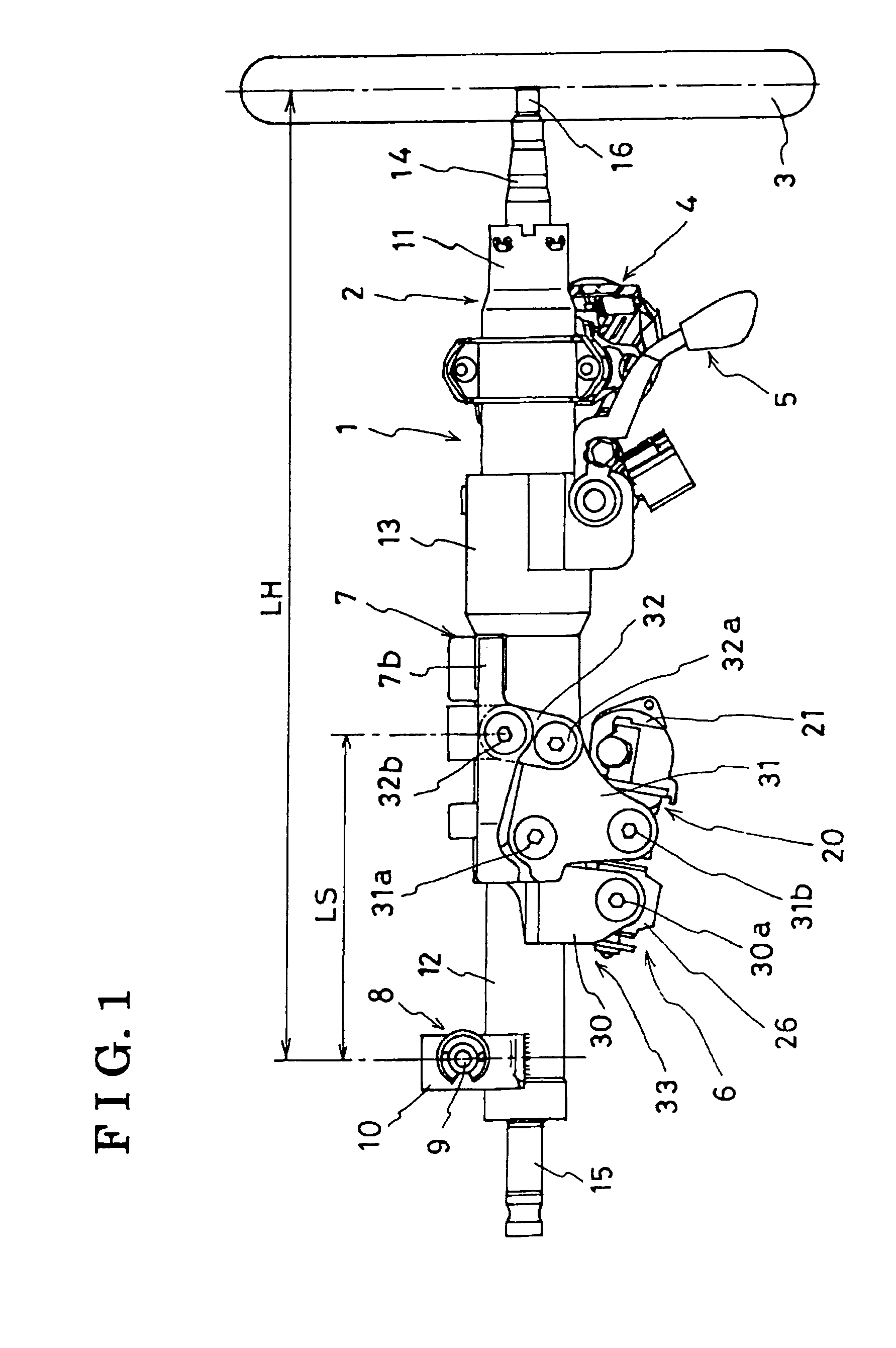
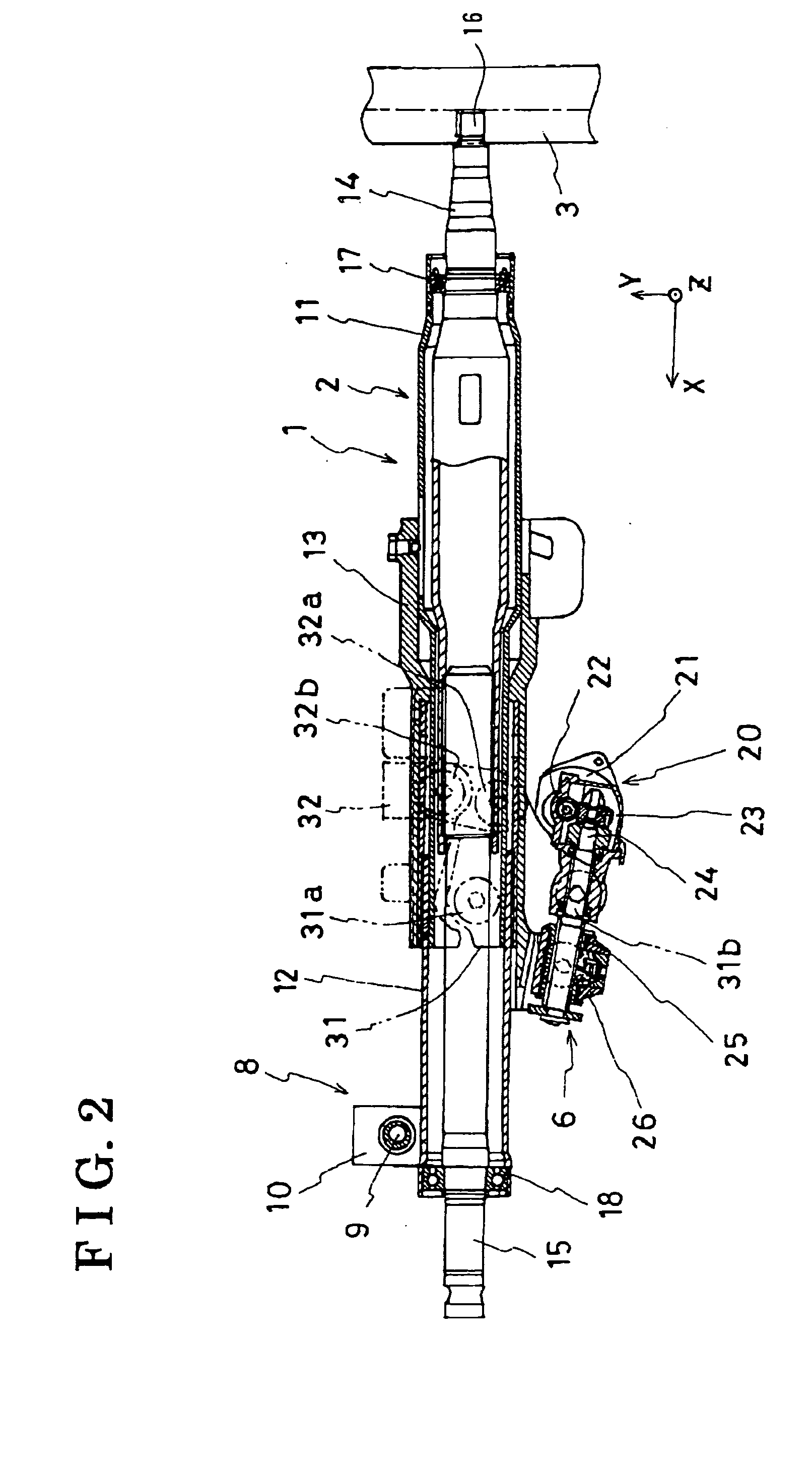
[0021]FIG. 1 shows a side-view of a steering apparatus 1 embedded in a vehicle according to the first embodiment of the present invention. FIG. 2 shows a partial cross-sectional view of the steering apparatus 1 showing an internal structure thereof.
[0022] The steering apparatus 1 mainly includes a steering column 2 provided in a diagonal direction relative to a back and forth direction of the vehicle, a steering wheel 3 attached to an end portion 16 of a first shaft 14 in the steering column 2 for a steering operation by a driver, a key cylinder 4 provided at the steering column 2 of the steering wheel 3 side operated by a vehicle key, a locking mechanism 5 for moving the steering wheel 3 in an axial direction of the steering wheel 3 and for locking the steering wheel 3 at a predetermined position where a driver intends to, a tilting mechanism 6 provided under the st...
second embodiment
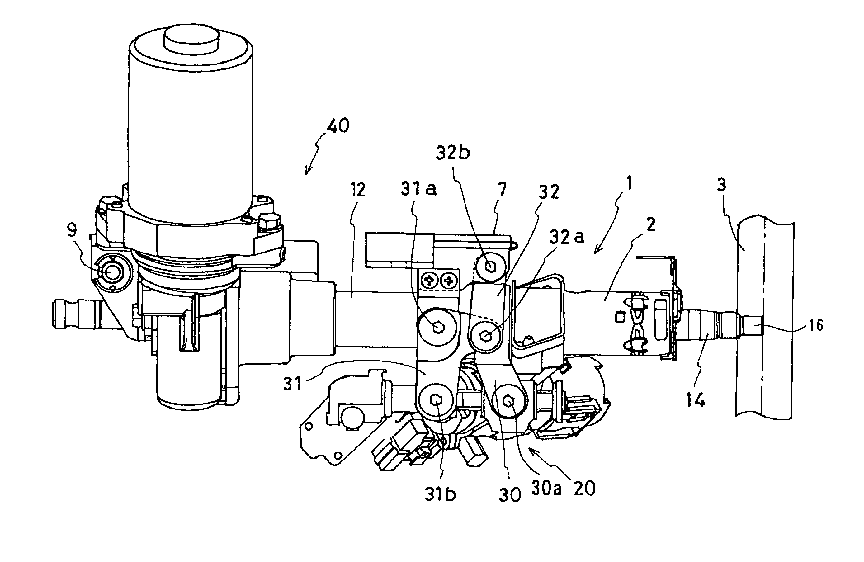
[0039] The power steering apparatus 40 is attached at a front portion of the second column tube 12. The power steering apparatus 40 includes a motor 41 for supporting a steering operation by an electric power, a decelerating mechanism 42 for supporting the steering operation by a driver by decelerating the output from the motor 41 by an internal gear. The motor 41 is formed as a single member with the decelerating mechanism 42 by a housing 43. The housing 43 is attached on an axis of the second column tube 12. The steering column 2 described above has a column swinging point 9 at a bracket 10 attached at a front portion of the housing 43. A front portion of the steering wheel 1 is attached to a supporting member of a vehicle body via the column swinging point 9. The steering apparatus 1 is also supported via a middle portion of the first column tube 11 and a column supporting point 32b to the supporting member of the vehicle body. The structure stated above in this section is alread...
PUM
 Abstract
Description
Claims
Application Information
 - R&D
- Intellectual Property
- Life Sciences
- Materials
- Tech Scout
- Unparalleled Data Quality
- Higher Quality Content
- 60% Fewer Hallucinations
Browse by: Latest US Patents, China's latest patents, Technical Efficacy Thesaurus, Application Domain, Technology Topic, Popular Technical Reports.
© 2025 PatSnap. All rights reserved.Legal|Privacy policy|Modern Slavery Act Transparency Statement|Sitemap|About US| Contact US: help@patsnap.com


