
Article carrier and bicycle rack system

a bicycle rack and article carrier technology, applied in the field of vehicle article carrier systems, can solve the problems of increased bicycle height, difficult use of attachments, and increased difficulty in driving,

Inactive Publication Date: 2005-04-21
SCHLACHTER BRADLEY S
View PDF23 Cites 23 Cited by
  • Summary
  • Abstract
  • Description
  • Claims
  • Application Information

AI Technical Summary

Benefits of technology

[0013] The foregoing has outlined some of the more pertinent features of the invention. These features should be construed to be merely illustrative....

Problems solved by technology

A main problem with conventional vehicle bicycle carrier systems of this type are that when a bicycle is secured to the top of a vehicle, the additional height of the bicycle makes driving more difficult and parking in standard garages impossible.
Indeed, in many circumstances, the additional height of the bicycle actually can cause a driving hazard.
While these and associated problems with top-mounted systems can be avoided by other, such as hitch-mounted, systems, still other problems exist.
Thus, for example, where the bicycle is attached to the hitch of a vehicle, the attachments that are employed are cumbersome and difficult to use.
Flat bed truck carrier systems, likewise, have problems of their own.
Thus, when a bicycle is secured horizontally in the truck bed, the bicycle often takes up the majority of the truck's cargo space.
If the bicycle is not rigidly secured, it may dislodge and create a driving hazard or damage the bicycle.
While these devices may be suitable for the particular purpose to which they address, they do not provide a unique, safe and secure method of attaching bicycles to vehicle article carrying systems for trucks and autos while also providing space efficiencies, security and ease of use.

Method used


Image

  • Article carrier and bicycle rack system
  • Article carrier and bicycle rack system
  • Article carrier and bicycle rack system

Examples


Embodiment Construction

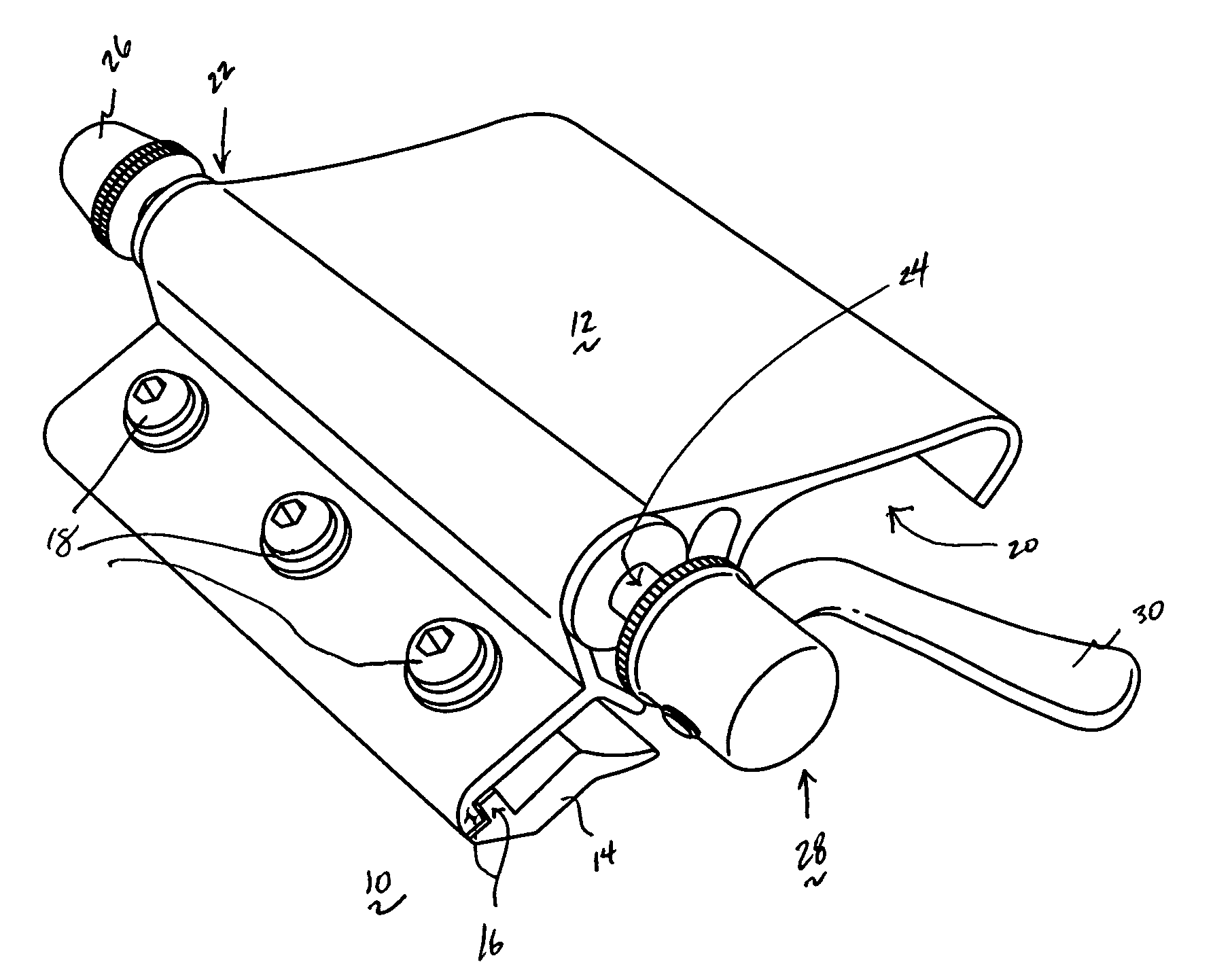
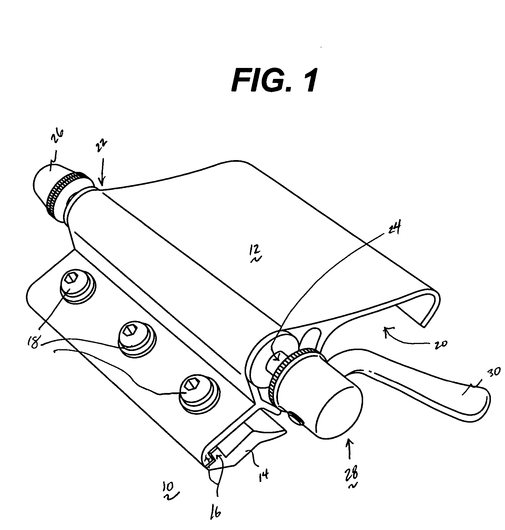
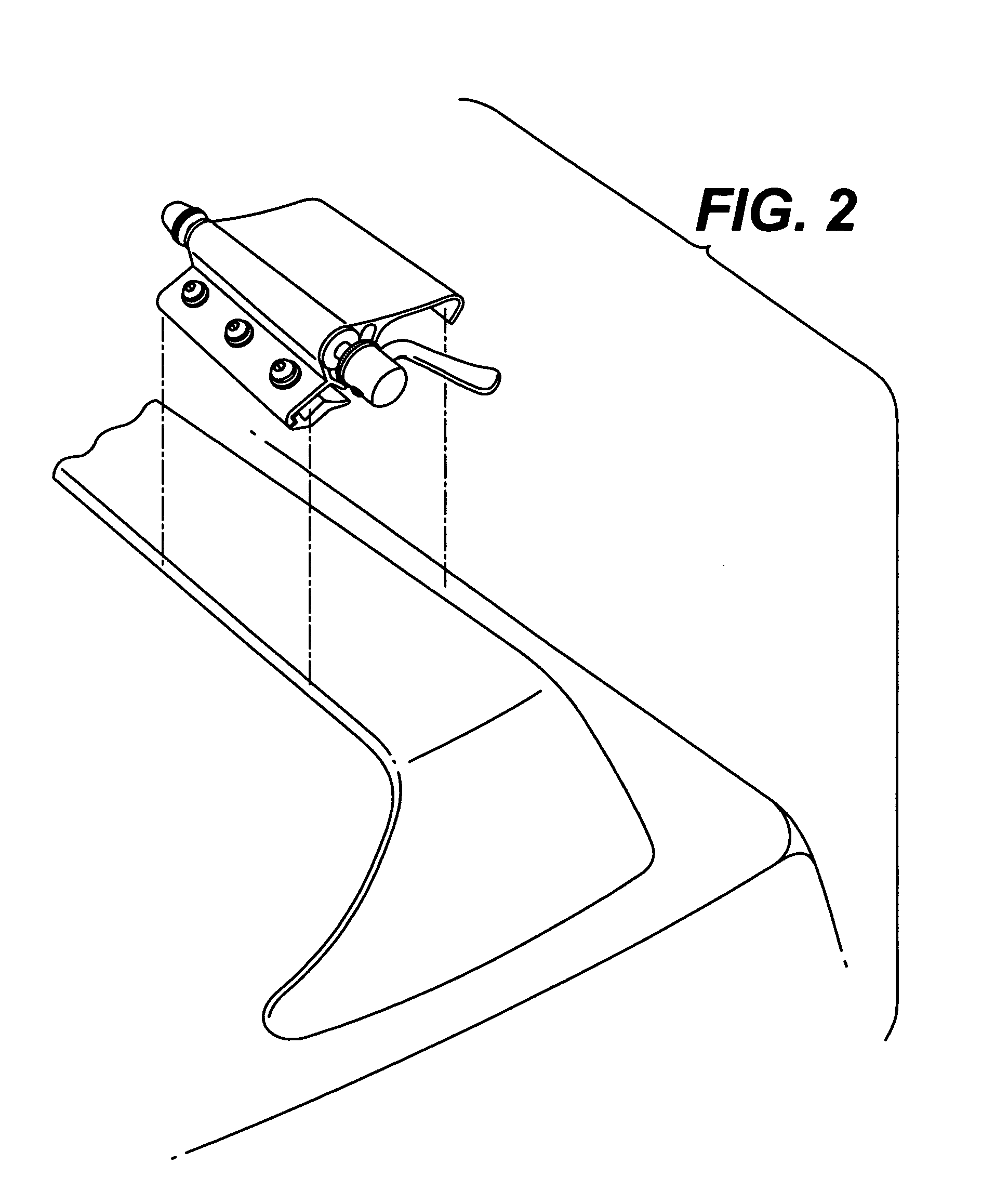
[0023] The present invention is adapted for use with various types of vehicles. For purposes of illustration only, one type of vehicle in which the invention may be implemented is a conventional pick-up style truck, such as the vehicle illustrated in FIG. 4. The truck 400 comprises a cab 402 having a roof 404. The roof 404 is a first support surface that extends in a generally horizontal plane designated by reference numeral 405. The bed area 406 of the truck is defined generally by a pair of opposing side panels 408 and 410, and a rear door 412. The bed 406 includes a floor 414. The floor 414 of the truck bed is a second support surface that extends in a generally horizontal plane designated generally by the reference number 415. As is self-evident, from an elevation or side view, first support surface 405 is located above second support surface 415. The present invention takes unique advantage of this planar relationship as will be seen. A system of the present invention is used t...


PUM


Abstract

An angled vehicle article carrier and bicycle rack system for providing a unique, safe and secure method of attaching bicycles to vehicle article carrying systems for trucks and autos while also providing space efficiencies, security and ease of use. The inventive device includes a single roof rail system that secures the front forks of a bicycle on the roof of a truck or vehicle and the rear tire being secured to the bed of a truck or the lower back portion of a vehicle. The roof rail system is attached to the roof of a vehicle. The front forks of the bicycle are secured to a mounting system that securely attaches to the roof rails. The mounting system securely attaches to single roof rail system and the bicycle forks attach to the mounting system. One end of the mounting system is endowed with a quick release apparatus that fastens or unfastens the bicycle forks. The security apparatus consists of an existing attachment system, whether a bracket, a bungee cord or a security strap, that secures the rear of the bicycle to either the bed of a truck or to the rear of a vehicle.

Description

BACKGROUND OF THE INVENTION [0001] 1. Field of the Invention [0002] The present invention relates generally to vehicle article carrier systems and, in particular, the invention relates to a system for providing a unique, safe and secure method of attaching bicycles or similar items to a vehicle, such as a sport utility vehicle, flat-bed pick-up truck, or other automobile, while also providing space efficiencies, security and ease of use. [0003] 2. Description of the Prior Art [0004] Vehicle article carrier systems have been in use for years. Typically, a vehicle article carrier system is comprised of a set of racks and associated devices that hold given articles in a horizontal position on the top of a car or van, or in the bed of a truck, or attached to a vehicle hitch. Bicycle carrier systems are especially popular, as bicycles are frequently transported. Numerous racks and devices have been devised to secure bicycles to vehicles during transport. One particularly common bicycle c...

Claims


Application Information

Patent Timeline
IPC IPC(8): B60R9/048B60R9/10
CPCB60R9/10B60R9/048
Inventor SCHLACHTER, BRADLEY S.
Owner SCHLACHTER BRADLEY S
Learn More