Method of providing electric power with thermal protection

Inactive Publication Date: 2005-04-21
PRATT & WHITNEY CANADA CORP
View PDF34 Cites 2 Cited by
  • Summary
  • Abstract
  • Description
  • Claims
  • Application Information

AI Technical Summary

Benefits of technology

[0009] In accordance with the present invention, an electric machine includes a ferrite portion, forming part of its rotor or stator that loses its magnetic characteristics above a certain chosen temperature. As a result, any magnetic flux circulating between the rotor and stator is significantly reduced above this temperature, and the machine stops acting as generator. Th

Problems solved by technology

This, in turn, limits the operating temperature of the windings,

Method used


Image

  • Method of providing electric power with thermal protection
  • Method of providing electric power with thermal protection
  • Method of providing electric power with thermal protection

Examples


Embodiment Construction

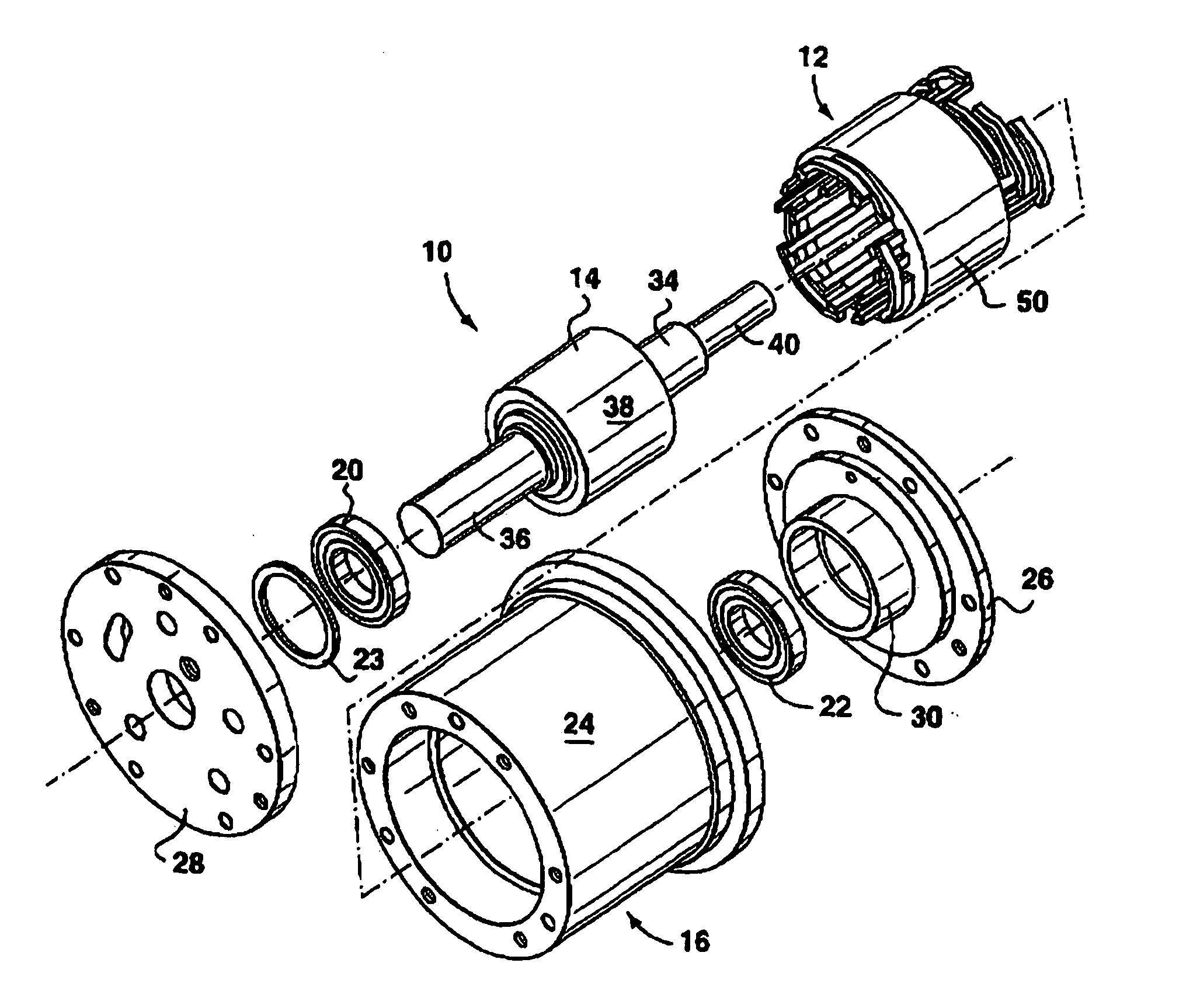
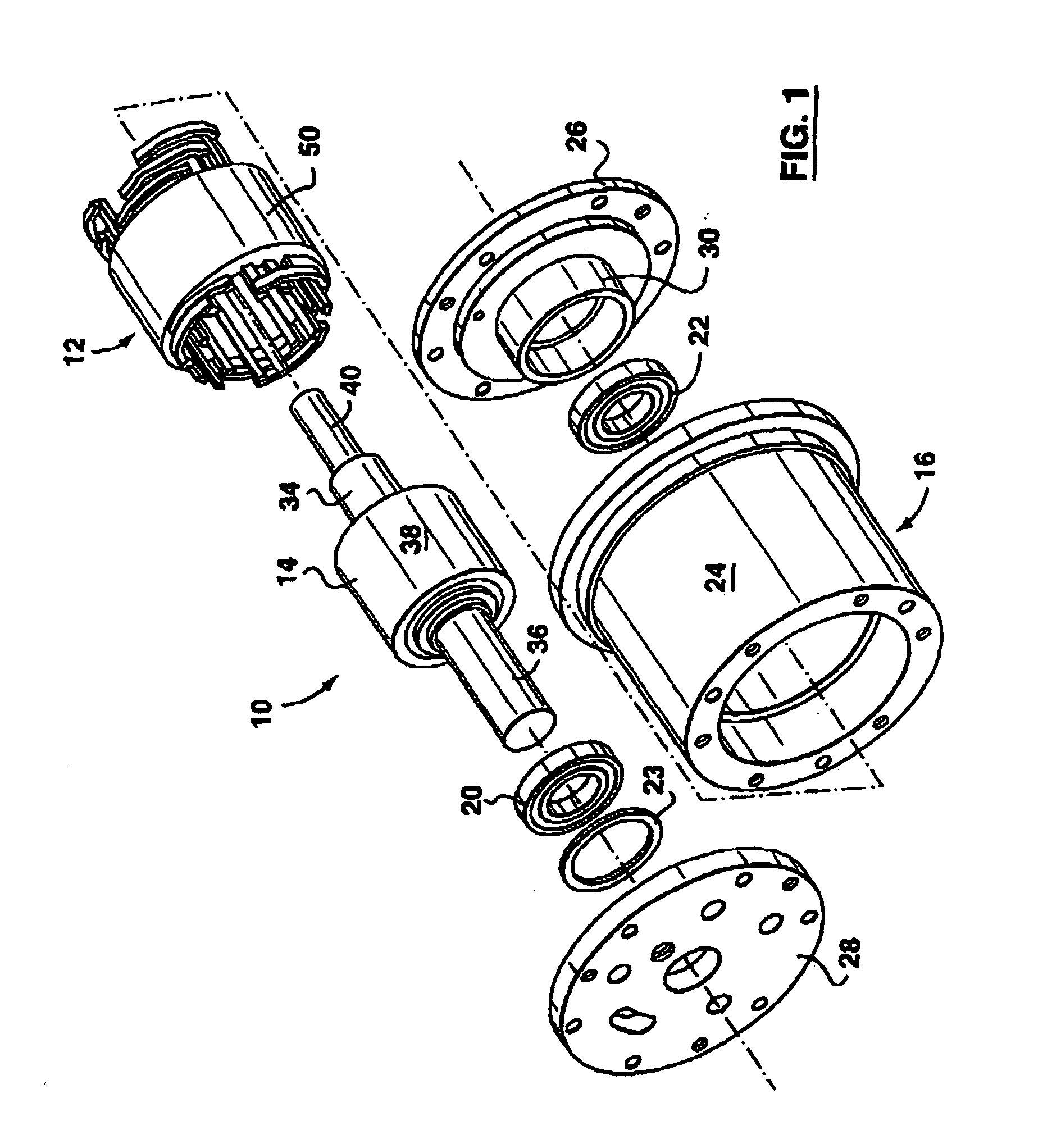
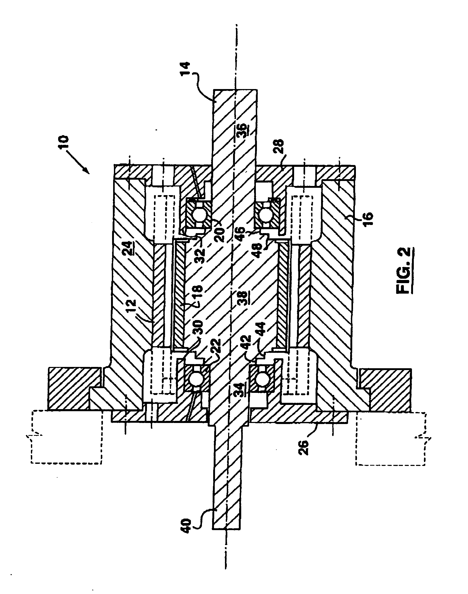
[0023]FIGS. 1 and 2 illustrate a permanent magnet electric machine 10, exemplary of an embodiment of the present invention. As illustrated, electric machine 10 includes a stator assembly 12 and rotor assembly 14, preferably mounted within a housing 16. Rotor assembly 14 is mounted for free rotation about its central axis within housing 16 by bearings 20 and 22.

[0024] Housing 16 includes an outer cylindrical shell 24, and generally disc shaped front and rear end plates 26 and 28. End plates 26 and 28 are fixed to shell 24, and thereby retain stator assembly 12, rotor assembly 14, and bearings 20 and 22 within housing 16. Annular walls 30 and 32 extend inwardly from the interior of end plates 26 and 28 and retain bearings 20 and 22 at defined axial positions within housing 16, about rotor assembly 14. A further retaining washer 23 assists to retain bearings 20 and 22. Housing 16 is preferably formed of high-grade stainless steel.

[0025] Example rotor assembly 14 includes a generally ...


PUM

PropertyMeasurementUnit
Temperatureaaaaaaaaaa

Abstract

An electric machine including a magnetic component, forming part of its rotor or stator that loses its magnetic characteristics above a certain chosen temperature is disclosed. This magnetic material forms part of a magnetic circuit that guides flux about the stator. As a result, any magnetic flux emanating with the rotor stops circulating about the stator above this temperature, and the machine stops acting as generator. The component is thermally coupled to windings carrying current from the machine's stator. The material forming the component is selected so that the chosen temperature is lower than the temperature at which the machine would be thermally damaged. This, in turn, limits the operating temperature of the windings, and thus prevents overheating of the machine during operation, typically caused by a fault. Preferably this magnetic material is formed from a ferrite material, such as a Manganese Zinc ferrite material.

Description

CROSS-REFERENCE TO RELATED APPLICATIONS [0001] This application is a continuation of application Ser. No. 09 / 949,855, which is a divisional application of Ser. No. 09 / 467,761, now U.S. Pat. No. 6,313,560.FIELD OF THE INVENTION [0002] The present invention relates to electric machines, and more particularly to electric generators that are thermally protected from damage resulting from high currents in such machines. BACKGROUND OF THE INVENTION [0003] Permanent magnet electric motors and generators are well known and understood. Typically, such permanent magnet machines include a rotor formed, at least in part, from a magnetic material such as Samarium-Cobalt. Electric windings on a stator about the rotor are used to carry current that either generates a magnetic field or is the result of a magnetic field about the rotor. As a motor, current through the windings induces the rotating magnetic field, which in turn applies a torque to the magnetic portion of the rotor causing it to act a...

Claims


Application Information

Patent Timeline
IPC IPC(8): H02K9/00H02K1/02H02K1/12H02K1/27H02K11/00H02K19/16H02K21/14
CPCH02K1/02H02K11/0047Y10T29/49009Y10T29/49073Y10T29/49174H02K11/25
Inventor DOOLEY, KEVIN ALLAN
Owner PRATT & WHITNEY CANADA CORP
Why Eureka
Try Eureka