
Eye massaging device

a technology of eye massaging and eye plate, which is applied in the field of eye massaging devices, can solve the problems of ineffective activation of eye blood circulation, inconvenient operation of vibration, and insufficient temperature control, so as to prevent transient blindness, effectively control operation temperature, and prevent transient blindness

Active Publication Date: 2017-11-30
YANG CHENG CHUAN
View PDF0 Cites 11 Cited by
  • Summary
  • Abstract
  • Description
  • Claims
  • Application Information

AI Technical Summary

Benefits of technology

The patent is about a device that can control the temperature of a water tank to prevent blindness caused by sudden changes in temperature. The device includes a thermal sensor and a microprocessor to regulate the heating of the water tank. Additionally, the device has two concave areas to prevent direct contact with the eyes and reduce any negative effects from hot patching.

Problems solved by technology

However, the vibration is not useful and it is not effectively to activate blood circulation of the eyes.
The above mentioned massagers have many drawbacks, but the applicant had developed an eye massaging device which may hot and ice compress the eyes, such as Taiwanese patent no.
However, the above mentioned eye massaging device still have some drawbacks which are described as follows.
Firstly, although it may activate the blood circulation, the temperature may be not controlled precisely.
Secondly, the eyes are not flat but convex.
Although the upper eyelids may isolate the water bag to prevent from directly contacting with the eyes and the eye massaging device is not directly adjust the temperature to the eyes (in fact, the tissues around the eyes are hot compressed), the lenses of the eyes may still feel uncomfortable.
Thirdly, the liquid temperature may be not effectively controlled only by the hot / cold chip.

Method used


Image

  • Eye massaging device
  • Eye massaging device
  • Eye massaging device

Examples


Embodiment Construction

[0025]To describe clearly that the present invention achieves the foregoing object and function, the technical features and desired function are described with reference to a preferred embodiment and accompanying drawings.

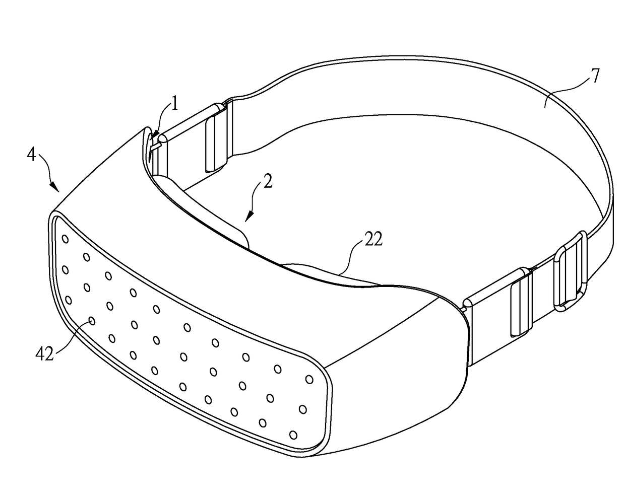
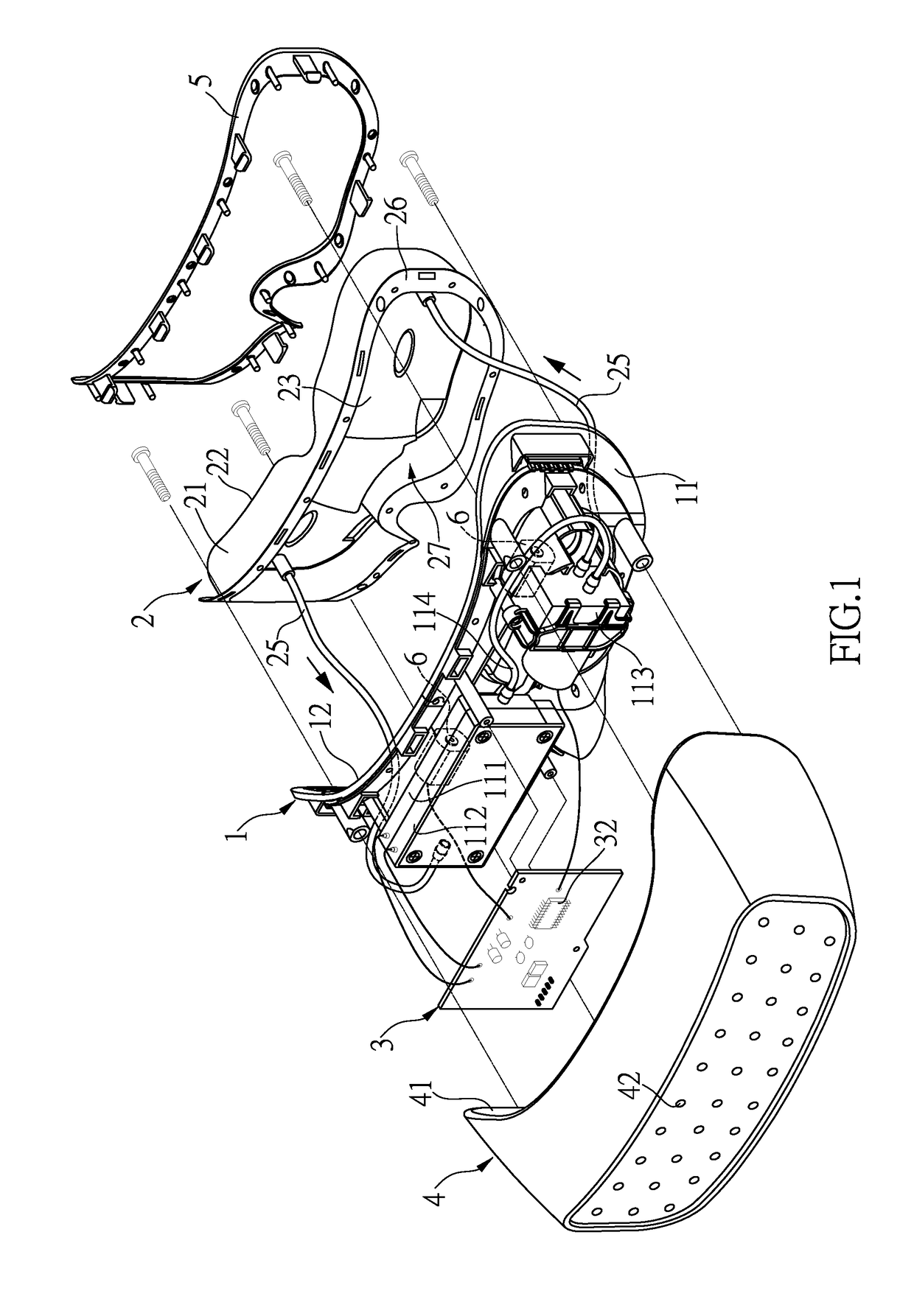
[0026]Please reference to FIGS. 1 to 4, an eye massaging device of the present invention may comprise a main body 1, a water bag 2, a control unit 3, a cover 4, and a fixing ring 5.

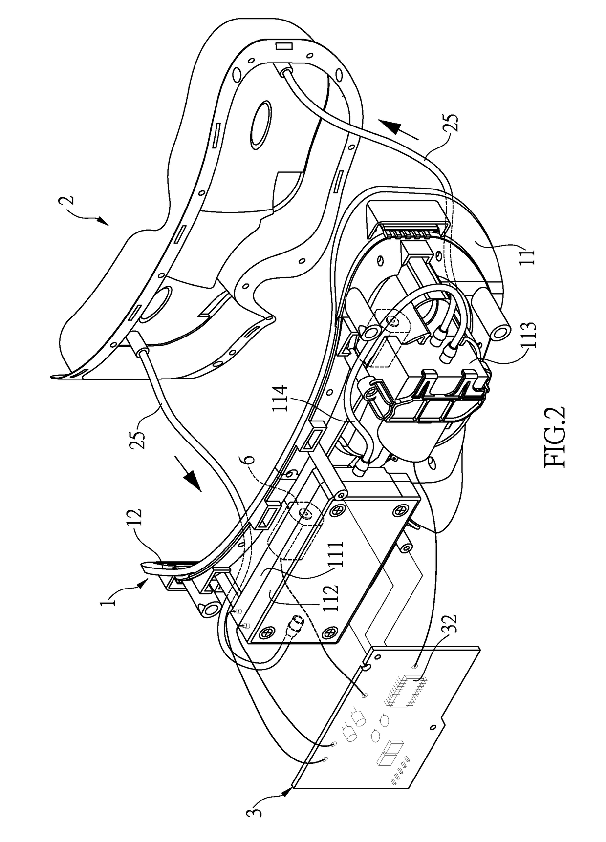
[0027]The main body 1 may have a front mounting portion 11 and a rear mounting portion 12 which are arranged opposite to each other. A circulating water tank 111, a heating member 112, and a circulating pump 113 are arranged on the front mounting portion 11. The heating member 112 is stacked on the circulating tank 111. The heating member 112 is fluidly communicated with the circulating water tank 111 via a heating pipe 114.

[0028]The main body 1 is an arc shell. The front mounting portion 11 is located at an arc convex side of the main body 1. The rear mounting portion 12 is located an a...


PUM


Abstract

An eye massaging device comprises a main body, a water bag, a control unit, a cover, and a fixing ring. The temperature of the circulating water tank may be sensed by a thermal sensor and then feedback the temperature signal to a microprocessor. The microprocessor may control to drive a heating member to increase temperature and stop increasing temperature so as to effectively control the operation temperature and prevent from transient blindness resulting from being not able to effectively control the temperature.

Description

BACKGROUND OF THE INVENTION1. Field of the Invention[0001]The present invention relates to a massaging device, more particular relates to an eye massaging device for hot compressing on the eyes and controlling the temperature.2. Description of Related Art[0002]The eyes are used frequently, such as watching the monitor, TV, or tablet so that the eyes may become tired and unwell. In order to ease the fatigue and uncomfortability of the eyes, besides the eyes must rest appropriately, the muscles and acupoints around the eyes may be massaged to ease the eyes. Therefore, many eye massaging devices are developed.[0003]The eye massaging device may be an airbag massager (such as Taiwanese patent no. M338070 and M288185) or a vibration massager for acupoints (such as Taiwanese patent no. M468311 and I314451). The convex particles of the airbag massager or the vibration massager may be activated by the motor to massage the eyes. However, the vibration is not useful and it is not effectively t...

Claims


Application Information

Patent Timeline
Patent Type & Authority Applications(United States)
IPC IPC(8): A61F7/08A61F7/00A61H23/02
CPCA61F7/08A61H23/02A61F7/0085A61F2007/0086A61H2201/5082A61F2007/0004A61H2201/0207A61F7/00A61F7/007A61F7/02A61F2007/0054A61F2007/0072A61F2007/0095A61F2007/0096A61F2007/0228A61H9/0028A61H2201/0242A61H2201/1604A61H2201/165A61H2201/1654A61H2205/024A61H2230/505A61H5/00A61H23/00A61H9/00
Inventor YANG, CHENG-CHUAN
Owner YANG CHENG CHUAN
Learn More