
Heat-seal apparatus and method thereof

a heat sealing and airbubble machine technology, applied in domestic applications, transportation and packaging, paper/cardboard articles, etc., can solve the problems of unsightly or incomplete closure, affecting the operation of the heating element, and need to be improved, so as to achieve rapid and uniform heating of the magnetically conductive heat sealing assembly, the effect of stably controlling and improving the quality of the sealing

Inactive Publication Date: 2019-02-14
CHIANG TUNG LUNG
View PDF0 Cites 0 Cited by
  • Summary
  • Abstract
  • Description
  • Claims
  • Application Information

AI Technical Summary

Benefits of technology

The present invention is a new type of air-bubble machine that uses electromagnetic heating and magnetically conductive heat-seal assemblies to heat-seal air-bubble films quickly and uniformly. The design of the machine ensures that the heating is done non-contactally, resulting in energy savings. The machine is also more stable and controllable. Overall, the invention solves traditional problems with air-bubble machines, making them more efficient and aesthetically pleasing.

Problems solved by technology

However, it is true that the following problems and lacks are still to be improved when the above-mentioned air-bubble machine is used:1. The conventional air-bubble machine uses the Nichrome wire combined with the roller as the heating element to heat by the electrical energization, the two ends of the Nichrome wire must be kept apart in order to prevent the Nichrome wire from short-circuiting.
Such that, the problem of unsightly or incomplete closure is produced.2. The heating element of the air-bubble machine is heated in a contact manner, which will affect the operation of the heating element and have a problem of excessive energy consumption.3. The heating element of the air-bubble machine can also be heated in a non-contact manner by infrared rays, but it has a problem that the heating efficiency is too low.

Method used


Image

  • Heat-seal apparatus and method thereof
  • Heat-seal apparatus and method thereof
  • Heat-seal apparatus and method thereof

Examples


Embodiment Construction

[0019]The following descriptions are exemplary embodiments only, and are not intended to limit the scope, applicability or configuration of the invention in any way. Rather, the following detailed description provides a convenient illustration for implementing exemplary embodiments of the invention. Various changes to the described embodiments may be made in the function and arrangement of the elements described without departing from the scope of the invention as set forth in the appended claims.

[0020]The foregoing and other aspects, features, and utilities of the present invention will be best understood from the following detailed description of the preferred embodiments when read in conjunction with the accompanying drawings.

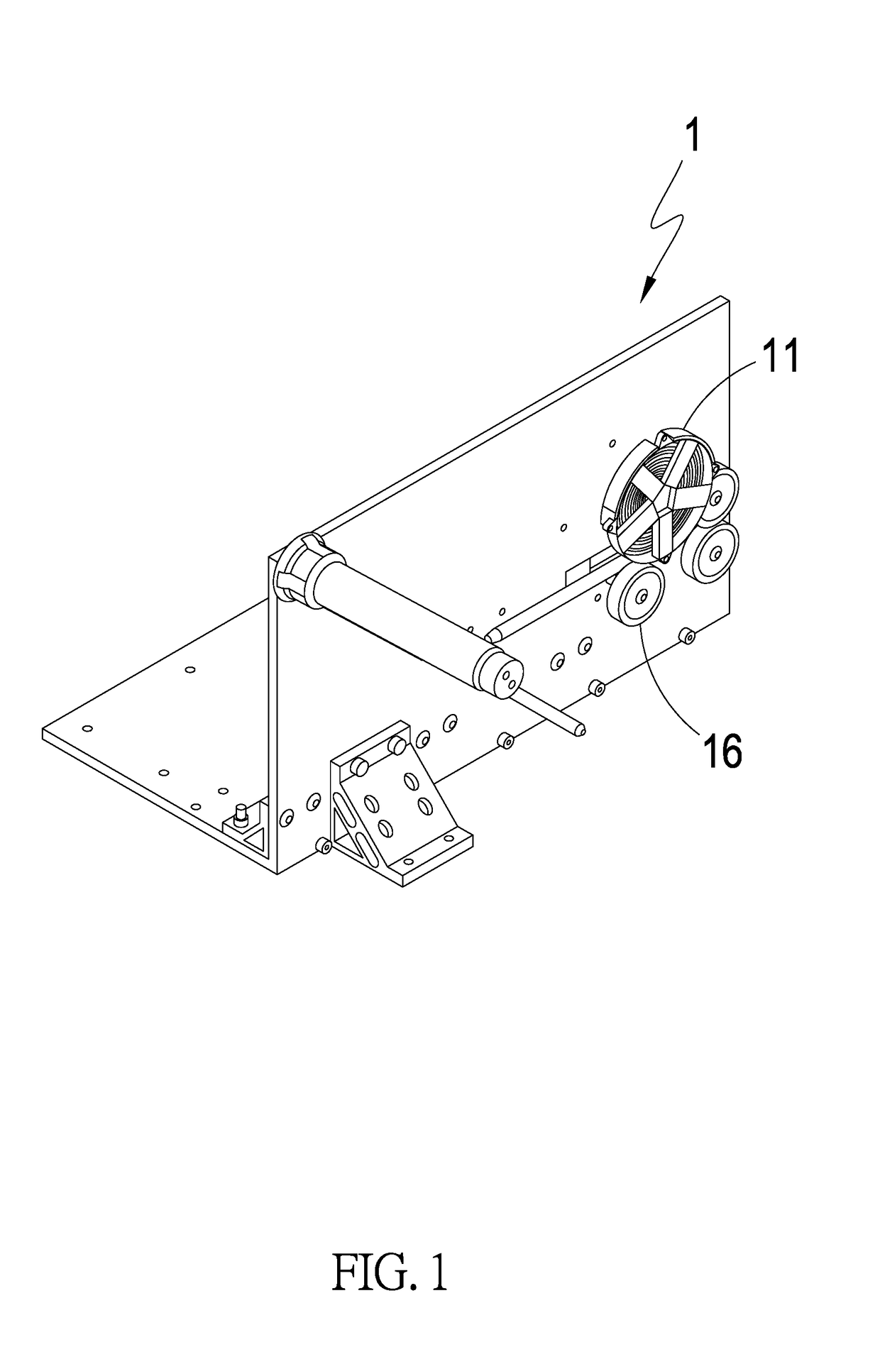
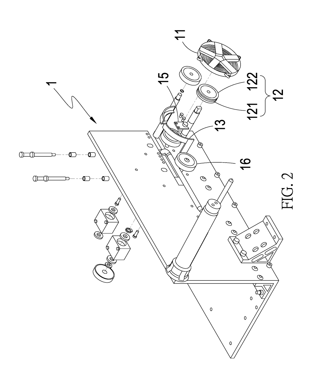
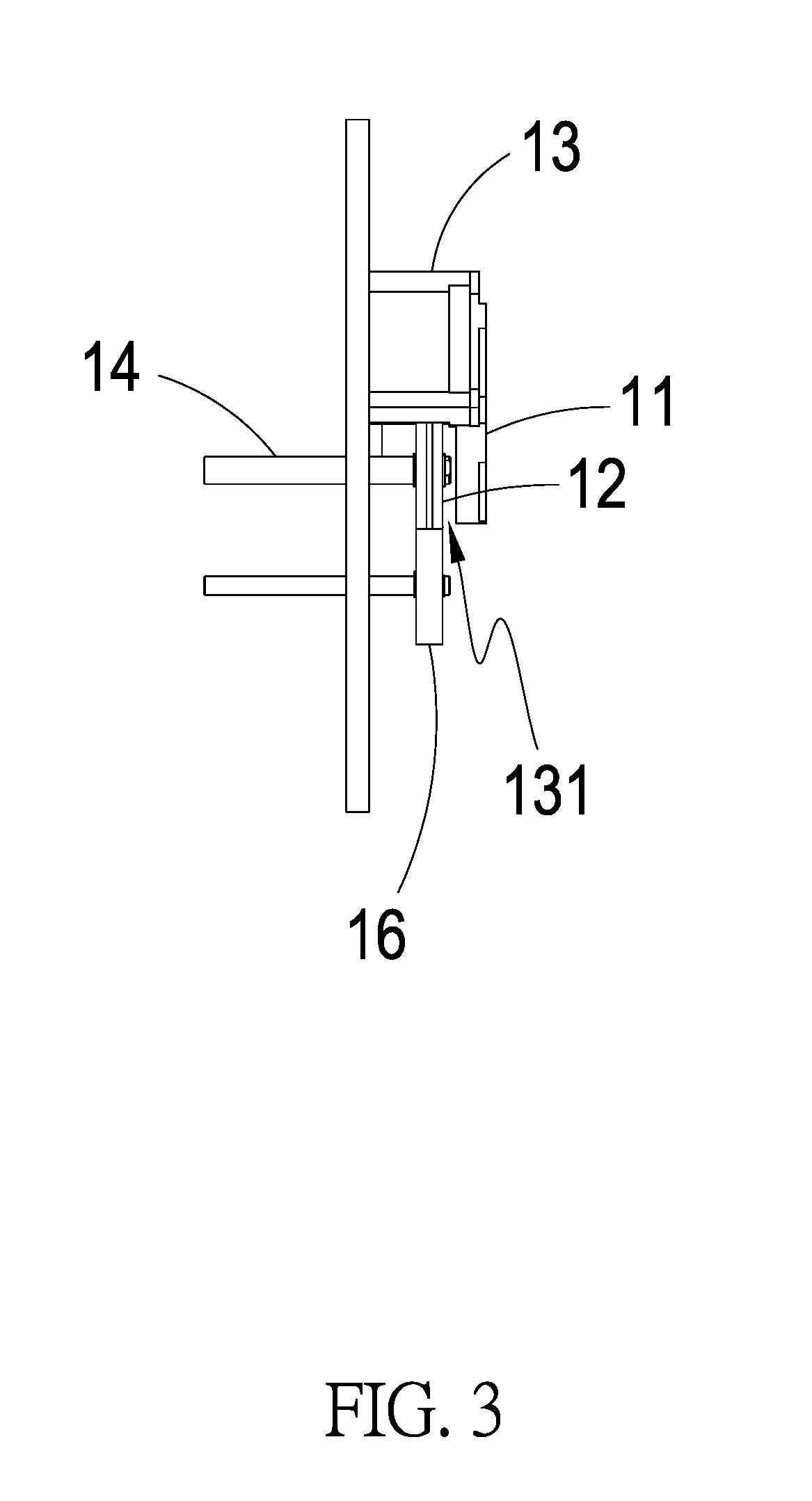
[0021]Please refer to FIG. 1 to FIG. 3 which are a perspective view to a partial side view of the preferred embodiment of the present invention. It can be clearly seen from the drawings that the present invention comprises: an air-bubble machine main-body 1 ...


PUM

PropertyMeasurementUnit
magnetic forceaaaaaaaaaa
magnetically conductiveaaaaaaaaaa
temperatureaaaaaaaaaa

Abstract

A heat-seal apparatus of an air-bubble machine and the method thereof, comprising: an air-bubble machine main-body; at least one electromagnetic heating assembly for producing a magnetic force; at least one magnetically conductive heat-seal assembly to heat-seal at least one air-bubble film; at least one support-portion to make an interval space between the electromagnetic heating assembly and the magnetically conductive heat-seal assembly; and at least one transmission shaft-body. The magnetic force generated by the electromagnetic heating assembly passes through the interval space to mutually interact with the magnetically conductive heat-seal assembly by electromagnetic induction, and the magnetically conductive heat-seal assembly is heated in a non-contact manner to make the heating be very rapid and uniform. The magnetically conductive heat-seal assembly is driven by the transmission shaft-body to move the air-bubble film which is simultaneously heat-sealed when being moved, thereby improving the use efficiency of energy.

Description

(a) TECHNICAL FIELD OF THE INVENTION[0001]The present invention provides a heat-seal apparatus of an air-bubble machine and the method thereof, and especially relates to an air-bubble machine and the method thereof which utilizes the electromagnetic induction to heat the magnetically conductive heat-seal assembly in a non-contact manner, so that the heating is more rapid and uniform, the operating temperature can be stably controlled, and the effect of saving energy can be achieved.(b) DESCRIPTION OF THE PRIOR ART[0002]The air-bubble film is an inflatable cushioning material used for packaging articles, and the air is poured into the closed bag-body, so that the bag-body is propped up to form a buffer protection structure.[0003]At present, the air-bubble film is a globally popular packaging material because its characteristics are in line with the requirements of the contemporary environmental protection and more effective utilization for storage space.[0004]And, it is more beautifu...

Claims


Application Information

Patent Timeline
Patent Type & Authority Applications(United States)
IPC IPC(8): B29C65/32B29C65/00
CPCB29C65/32B29C66/91231B29C66/91421B29C66/72B29L2007/008B29C65/224B29C66/0042B29C66/1122B29C66/439B29C66/8122B29C66/83413B29C66/961B29L2031/7138B31D5/0073B31D2205/0088B29K2905/12B29K2905/08B29K2827/18B65D81/03
Inventor CHIANG, TUNG-LUNG
Owner CHIANG TUNG LUNG
Learn More