Nitriding method and device

A technology of nitriding treatment and temperature detection device, which is used in ion implantation plating, coating, instruments, etc.

Inactive Publication Date: 2006-08-30
HONDA MOTOR CO LTD
View PDF2 Cites 4 Cited by
  • Summary
  • Abstract
  • Description
  • Claims
  • Application Information

AI Technical Summary

Problems solved by technology

Depending on the particular situation, various inconveniences are caused, which lead to arc discharge, and a part of the surface of the workpiece is melted, and / or it is impossible to apply any uniform nitriding treatment

Method used


Image

  • Nitriding method and device
  • Nitriding method and device
  • Nitriding method and device

Examples


Embodiment Construction

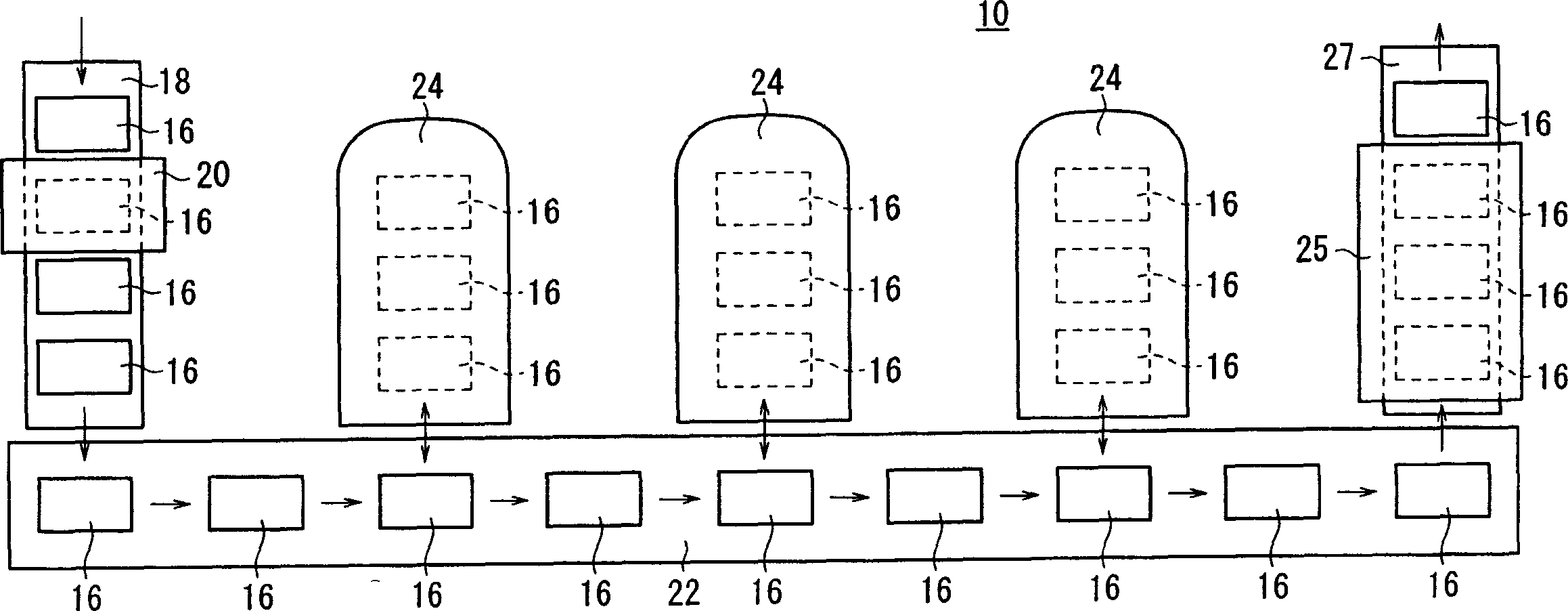
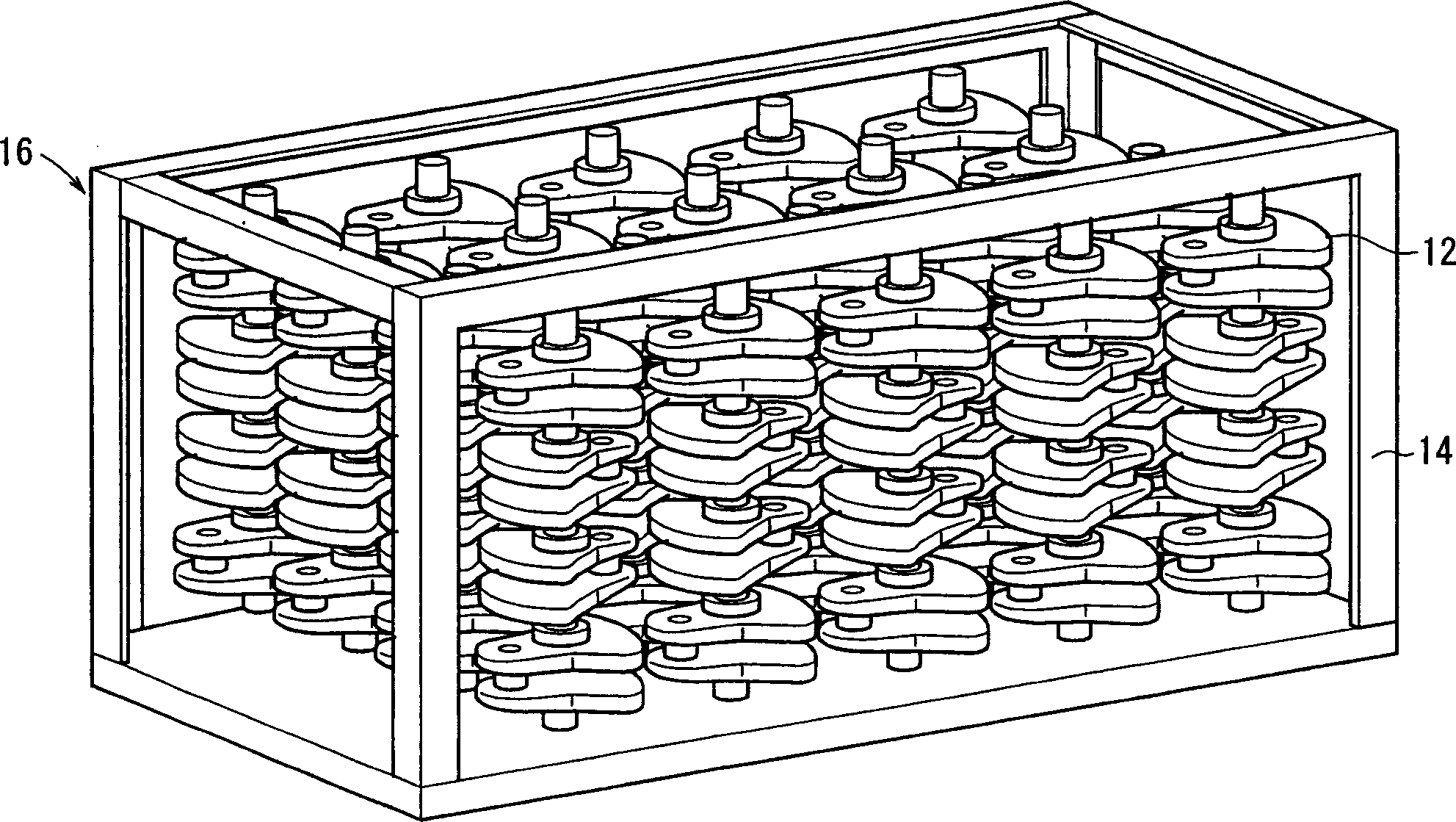
[0022] figure 1 A schematic arrangement of a nitriding treatment system 10 including a nitriding treatment device according to an embodiment of the present invention is shown. Such as figure 2 As shown, a plurality of crankshafts 12 as workpieces are fed to the nitriding treatment system 10 in the form of a hopper 16 in which the plurality of crankshafts 12 are positioned with a clamp 14 .

[0023] The nitriding treatment system 10 includes a washing machine 20 which, for example, removes dust and oil adhering to the crankshaft 12 conveyed by a conveyor 18 from which the washed crankshaft 12 is received to clean them. Conveyor 22 that transfers to each workbench, transverse type heat treatment furnace 24 that is installed on a plurality of workbenches along conveyor 22, and cooling box 25 that cools through the connection Crankshaft 12 conveyed by conveyor 27 to the terminal end of conveyor 22 .

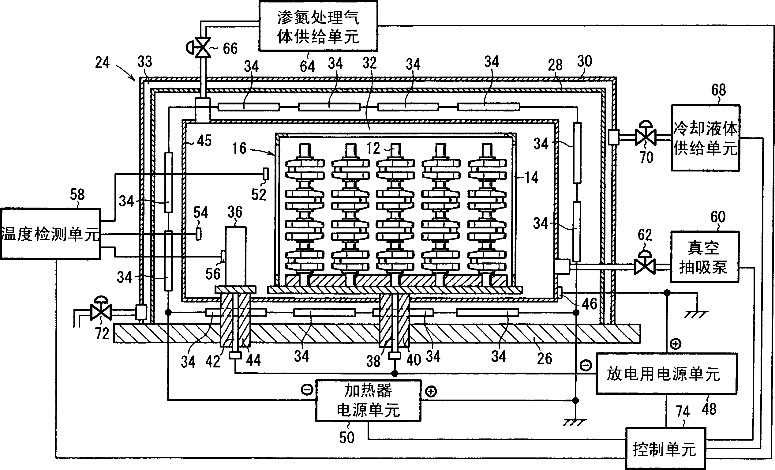
[0024] FIG. 13 shows the arrangement of the transverse type heat treatment f...


PUM


Abstract

A pulse voltage having a frequency of 15 kHz is applied from a discharging power supply unit (48) to between a crankshaft (12) and an electrode plate (45) at a current density of 2.5 mA / cm2 to generate a glow discharge and an electric heater (34) is driven at a 40% output (64 kW / kg) to heat the crankshaft (12) to up to 400 DEG C, and then heating is continued with the current density of a glow discharge set at 0.5 mA / cm2 and the output of the electric heater (34) set at 90% (144 kW / kg), thereby effecting nitriding at a desired nitriding temperature.

Description

technical field [0001] The invention relates to a nitriding treatment method and a nitriding treatment device for nitriding a workpiece in a heat treatment furnace. Background technique [0002] Nitriding treatment exists in a process in which the surface of a workpiece composed of a steel material is nitrided to form an iron nitride layer, so that the surface of the workpiece is hardened. Nitriding treatment is widely performed. Methods for nitriding treatment include plasma nitriding treatment in which plasma heating is performed by glow discharge. [0003] In the case of such processing, when the workpiece is cold, the glow discharge becomes unstable. Depending on the circumstances, various inconveniences are caused such that arc discharge is caused, and a part of the surface of the workpiece is melted, and / or it is impossible to apply any uniform nitriding treatment. In particular, when the temperature distribution of the workpiece is non-uniform, it is impossible to ...

Claims


Application Information

Patent Timeline
Patent Type & Authority Applications(China)
IPC IPC(8): C23C8/36H05H1/46C21D1/06
CPCC23C8/36C23C14/3485C23C14/548G05B13/02
Inventor 竹内丰唐泽均小岛秀男
Owner HONDA MOTOR CO LTD
Why Eureka
Try Eureka