Light device having light concentrating device

a technology of concentrating device and light device, which is applied in the direction of fixed installation, lighting and heating apparatus, instruments, etc., can solve the problem of devices without concentrating device, and achieve the effect of increasing the light projecting distan

Inactive Publication Date: 2005-04-21
TAICHANG SYST CONTROL
View PDF8 Cites 2 Cited by
  • Summary
  • Abstract
  • Description
  • Claims
  • Application Information

AI Technical Summary

Benefits of technology

[0007] The primary objective of the present invention is to provide a projector light device having a light concentrating device including a light concentrating device for concentrating the light, and for increasing the light projecting distance.
[0008] In accordance with one aspect of the invention, there is provided a projector light device comprising a housing including a supporting panel provided therein, a board attached to the panel, a plurality of light members attached to the board for generating lights, and a plate disposed in front of the board, and including at least one lens provided therein and arranged in front of the light members, for concentrating the lights generated by the light members, and for increasing projecting distances of the lights generated by the light members.
[0010] A cover may further be provided and disposed in front of the plate, and including a transparent sheet provided therein, and arranged in front of the light members, for shielding and protecting the light members, and for allowing the light generated by the light members to emit out through the transparent sheet of the cover.

Problems solved by technology

However, the typical projector light devices have no devices for concentrating the light, such that the light generated by the typical projector light devices may only be emitted for a projecting distance of about 20 to 25 meters only, such that the objects farther than 25 meters may not be clearly lighted by the typical projector light devices.

Method used


Image

  • Light device having light concentrating device
  • Light device having light concentrating device
  • Light device having light concentrating device

Examples


Embodiment Construction

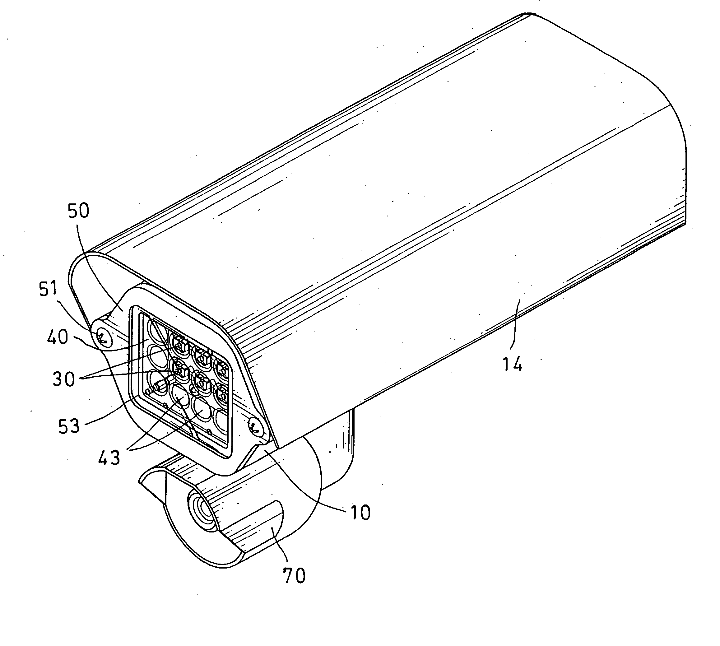
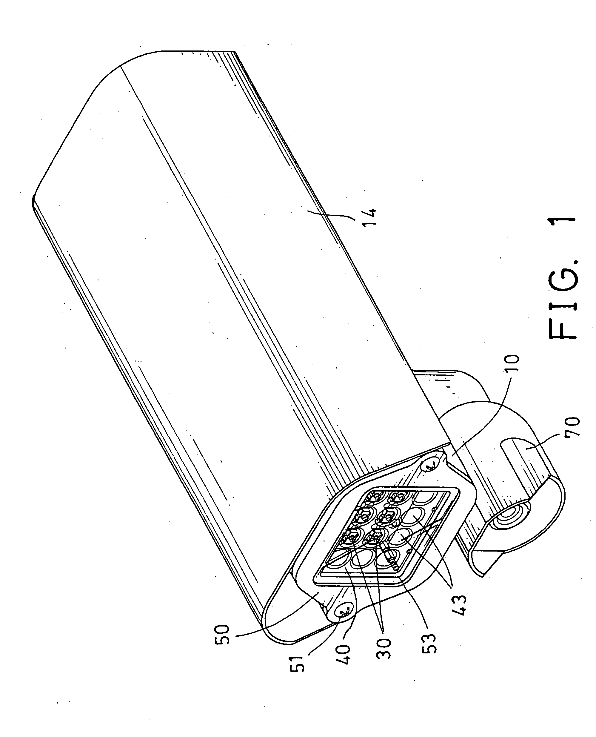
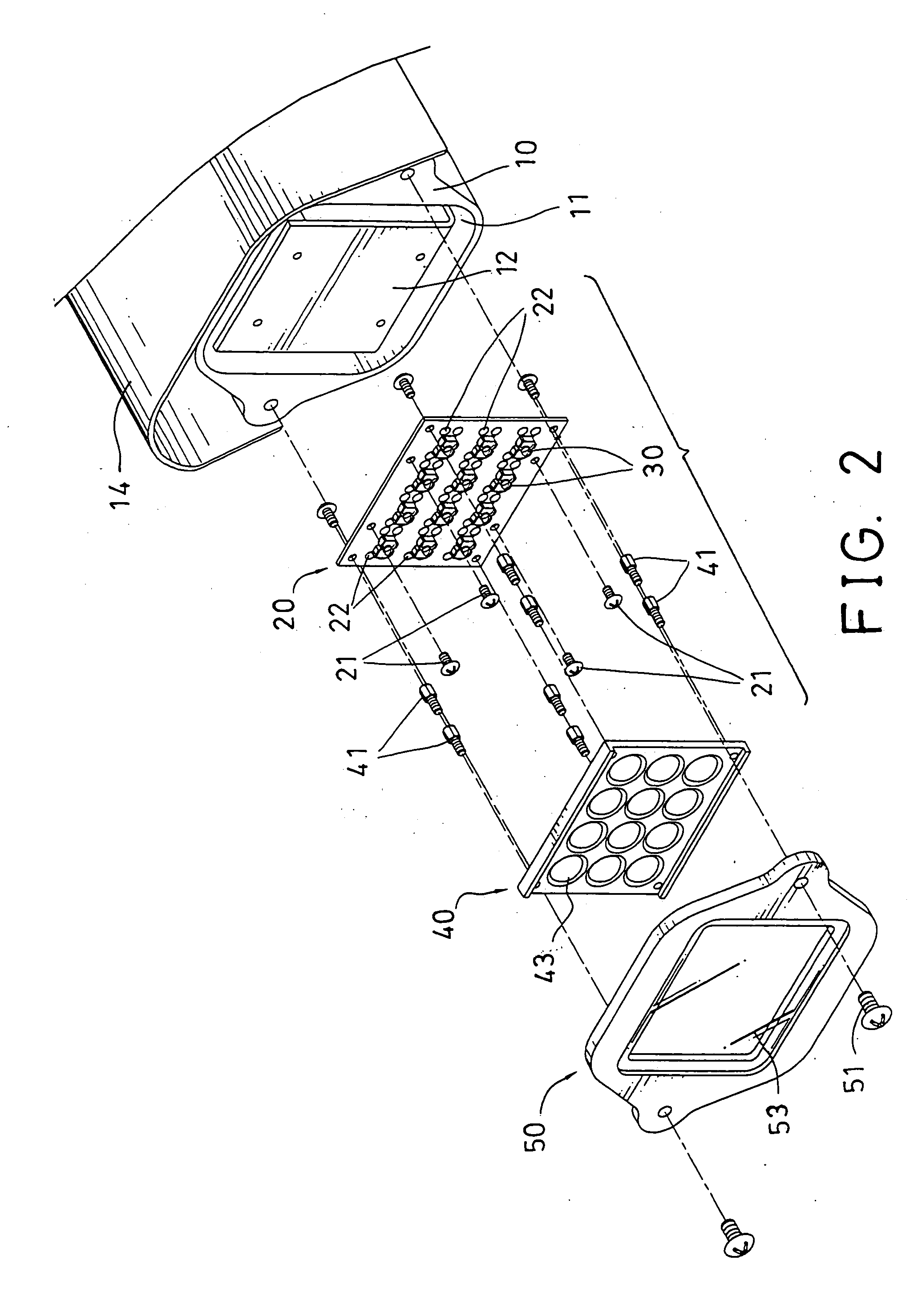
[0019] Referring to the drawings, and initially to FIGS. 1-4, a projector light device in accordance with the present invention comprises a housing 10 including a chamber 11 formed therein for receiving a supporting panel 12 therein, and a hood 14 attached onto the housing 10, for shielding or protecting the housing 10 from sun shine and rain, or the like.

[0020] A board 20, such as a circuit board 20 is secured to the panel 12 with fasteners 21, for supporting one or more light members 30 thereon, and includes a number of holes or conductors 22 applied or provided thereon. As shown in FIG. 5, each of the light members 30 includes a seat 31 having an orifice 32 formed therein for receiving a light element 33 therein, such as the light bulbs, the light emitting diodes, etc.

[0021] Each of the light members 30 further includes one or more pairs of conductors 34, 35 extended therefrom and coupled to the light element 33, and engaged through or coupled to the conductors 22 of the circui...


PUM


Abstract

A projector light device includes a housing having a supporting panel, a board attached to the panel, one or more light members attached to the board for generating lights, and a plate disposed in front of the board and having one or more lenses arranged in front of the light members, for concentrating the lights generated by the light members, and for increasing projecting distances of the lights generated by the light members. Each of the light members includes a seat having an orifice for receiving a light element. A cover may be disposed in front of the plate, and a camera may be attached to the housing for video taping purposes or for taking pictures.

Description

BACKGROUND OF THE INVENTION [0001] 1. Field of the Invention [0002] The present invention relates to a projector light device, and more particularly to a projector light device having a light concentrating device for concentrating the light, and for increasing the light projecting distance. [0003] 2. Description of the Prior Art [0004] Typical projector light devices have been provided for project light beams onto far away objects, and comprise a number of light members, such as the typical light bulbs, the light emitting diodes, etc. attached to a board. [0005] However, the typical projector light devices have no devices for concentrating the light, such that the light generated by the typical projector light devices may only be emitted for a projecting distance of about 20 to 25 meters only, such that the objects farther than 25 meters may not be clearly lighted by the typical projector light devices. [0006] The present invention has arisen to mitigate and / or obviate the afore-des...

Claims


Application Information

Patent Timeline
Patent Type & Authority Applications(United States)
IPC IPC(8): F21S8/10F21V5/04F21V19/00F21V33/00G03B21/18
CPCF21S48/1154F21V5/007F21V5/04F21Y2105/001F21V33/0052F21Y2101/02F21V19/0055F21Y2105/10F21Y2115/10
Inventor HUANG, MING HUANG
Owner TAICHANG SYST CONTROL
Why Eureka
Try Eureka