Throwing type inflatable liferaft release device for tugboat

A technology for releasing devices and life rafts, which is applied in the direction of devices for throwing or releasing ships, devices for guiding ships to the water surface, etc. It can solve the problems of large shaking of the ship hull, potential safety hazards of ships, and life rafts falling on the deck, etc. problems, to achieve a wide range of applications, ensure personal safety, and lengthen the effect of throwing distance

Inactive Publication Date: 2018-12-07
天津港轮驳有限公司
View PDF0 Cites 1 Cited by
  • Summary
  • Abstract
  • Description
  • Claims
  • Application Information

AI Technical Summary

Problems solved by technology

[0003] At present, in addition to the base and bracket, most tugboats have only a vertical guide rod with a limited length. The length of the guide rod directly affects the effective distance for the liferaft to be thrown from the hull. There is a certain distance between the upper navigation deck where the tugboat’s inflatable liferaft is located and the side of the ship, and a circle of side rails are tied outboard on both sides of the tugboat, which forms an obstacle to the throwing route of the liferaft. During the life raft release process, the life raft often deviates to one side and falls on the deck; some tugboats use extended and foldable guide rods, but the extended guide rods are poor in wind and wave resistance and stability. The hull shakes a lot, and the release of the life raft often causes the life raft to fall from one side of the deck and get stuck on the guide rod, which makes the ship a great safety hazard, and the safety of the people on board cannot be guaranteed

Method used


Image

  • Throwing type inflatable liferaft release device for tugboat
  • Throwing type inflatable liferaft release device for tugboat

Examples


Embodiment Construction

[0022] Below in conjunction with accompanying drawing and specific embodiment the present invention is described in further detail:

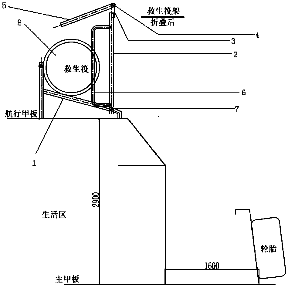
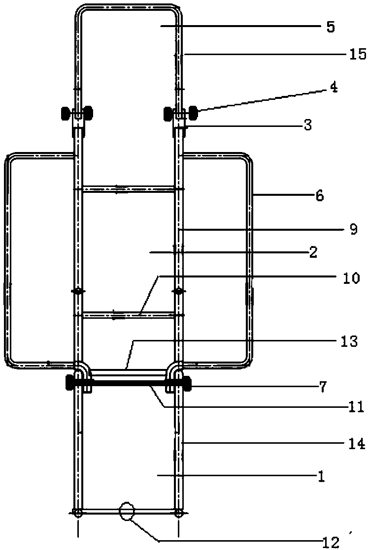
[0023] Such as figure 1 and figure 2 As shown, a throwing type inflatable liferaft release device for tugboats includes: a base 1, a first extended support frame 2, a guide rail 3, bolts and nuts 4, a second extended support frame 5, a balance rail 6, and a nut 7 , guide rod 9, cross bar 10, through bolt 11, hydrostatic pressure releaser 12, base front end cross bar 13, base guide rod 14 and second extension support frame guide rod 15, wherein the first extension support frame 2 comprises a pair of balance Railing 6, nut 7, guide rod 9, cross bar 10 and through bolt 11, life raft 8 is the inherent life-saving equipment of tugboat. The first extension support frame 2 is connected to the front end of the base 1 through nuts 7 and through bolts 11, and two cross bars 10 are arranged in the middle of the guide rod 9, and left and right symmetrica...


PUM


Abstract

The invention discloses a throwing type inflatable liferaft releasing device for a tugboat, which comprises a liferaft base and two articulated extension supports and a liferaft release mechanism, thebase is a tilted support frame with low front part and high rear part, A rear end of that base extend upwardly perpendicular and out of the bracket, The life raft releasing mechanism is fixed on thecross bar at the rear end of the base, the first extension support frame is a frame structure and is articulated with the upper side of the front end of the base guide bar, the two sides of the guidebar are respectively provided with left and right symmetrical balancing railings, the lower end of the second extension support frame is articulated with the upper end of the first extension support frame through the guide rail, and is inclined to abut on the upper part of the first extension support frame. As that life raft is release, the life raft is rolled down by the dead weight and the two extend supports are pushed apart to form the same rolling plane with the base, and the balance railings on both sides play a balancing and guiding role, so that the inflatable life raft is smoothly rolled off the slideway and enters water quickly under any sea condition; The throwing type inflatable liferaft releasing device has the advantages of simple structure, convenient installation, low costand wide application range.

Description

technical field [0001] The invention relates to ship emergency lifesaving equipment, in particular to a throwing-type inflatable liferaft release device for tugboats, which belongs to the technical field of ship equipment. Background technique [0002] Throwable inflatable liferaft is a kind of emergency lifesaving equipment at sea. When a ship encounters a shipwreck, the hydrostatic pressure release device can be manually opened to release it and thrown into the overboard water. The liferaft is released from its own inflatable cylinder. The mixed gas makes it inflated and shaped to float on the water surface, and the crew is rescued in the life raft in sea water. Throwable inflatable liferaft occupies a small deck area, is easy to operate, and has a fast lifesaving effect. It is the main lifesaving equipment of the port tugboat and is usually fixed in the liferaft frame on the upper navigation deck of the tugboat. [0003] At present, in addition to the base and bracket, m...

Claims


Application Information

Patent Timeline
Patent Type & Authority Applications(China)
IPC IPC(8): B63B23/32B63B23/28
CPCB63B23/32B63B23/28
Inventor 刘玉平孙波伊杰高文泽王志林窦树利李鑫
Owner 天津港轮驳有限公司
Why Eureka
Try Eureka