
Photoreceptor unit

Inactive Publication Date: 2005-04-21
S PRINTING SOLUTION CO LTD
View PDF5 Cites 4 Cited by
  • Summary
  • Abstract
  • Description
  • Claims
  • Application Information

AI Technical Summary

Benefits of technology

[0026] A spring member that elastically supports the handgrip may be further provided to prevent the handgrip from being in close contact with the housing.
[0029] When the housing is inserted into an image forming apparatus and the transfer unit is placed on the top of the housing, the handgrip is pressed down by the transfer unit and comes close to the housing. When the transfer unit is separated from the housing, the handgrip is slightly separated from the housing by a reaction force of the spring member to allow a user to easily grip the handgrip.
[0030] According to another aspect of the present invention, a photoreceptor unit comprises a photoconductive drum assembly; a housing to enclose the photoconductive drum assembly to be rotatable therein; a handgrip rotatably connected to the housing; and a spring member to resiliently support the handgrip to prevent the handgrip in a laid-down position from being in tight contact with the casing by its own weight.

Problems solved by technology

However, if the handgrip is not provided at the center of gravity of the photoreceptor unit, it will be difficult for the user to lift up or move the photoreceptor unit with one hand.
As a result, the photoconductive drum or the printer mainframe may be damaged during the mounting of the photoreceptor unit.

Method used


Image

  • Photoreceptor unit
  • Photoreceptor unit
  • Photoreceptor unit

Examples


Embodiment Construction

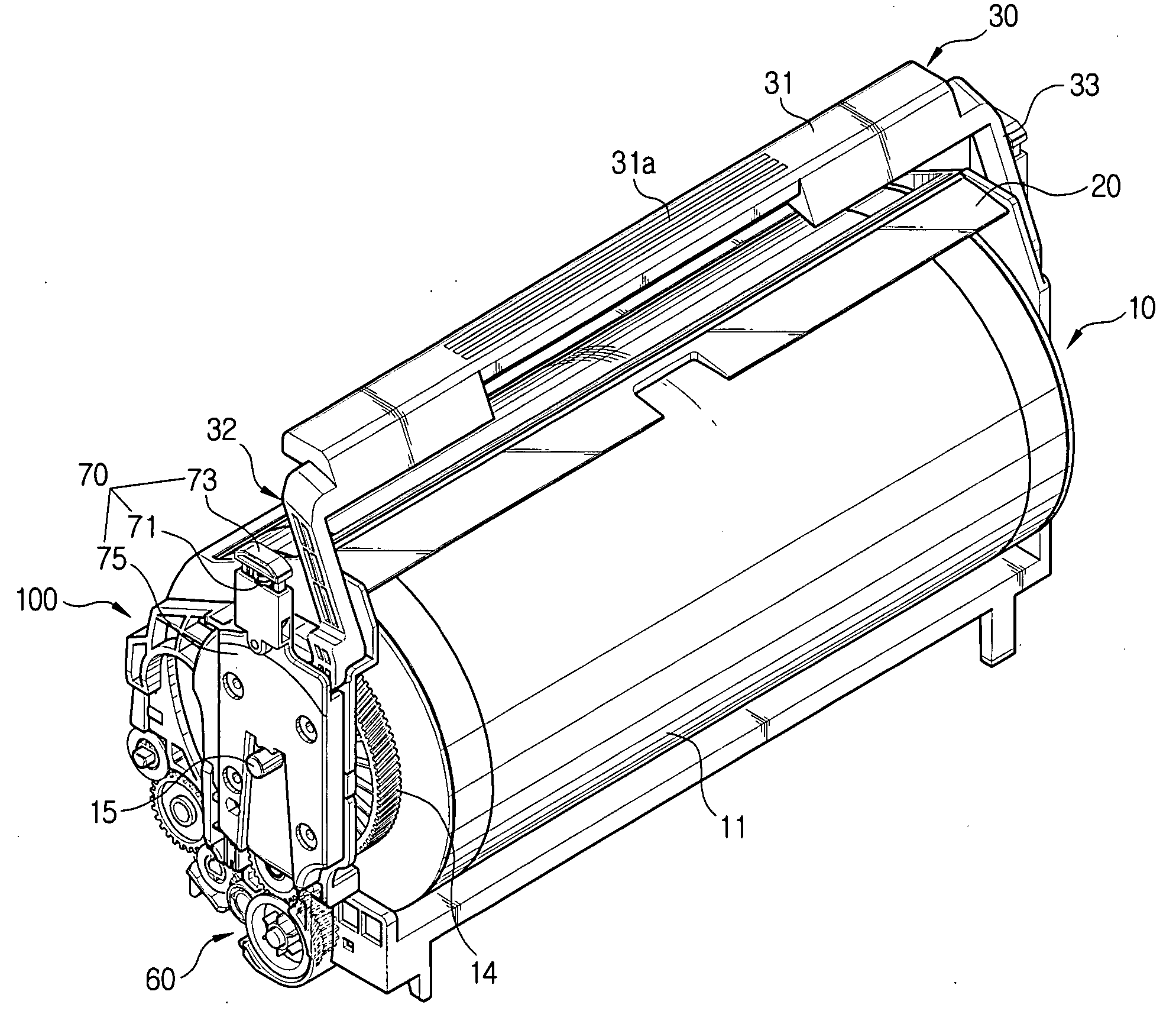
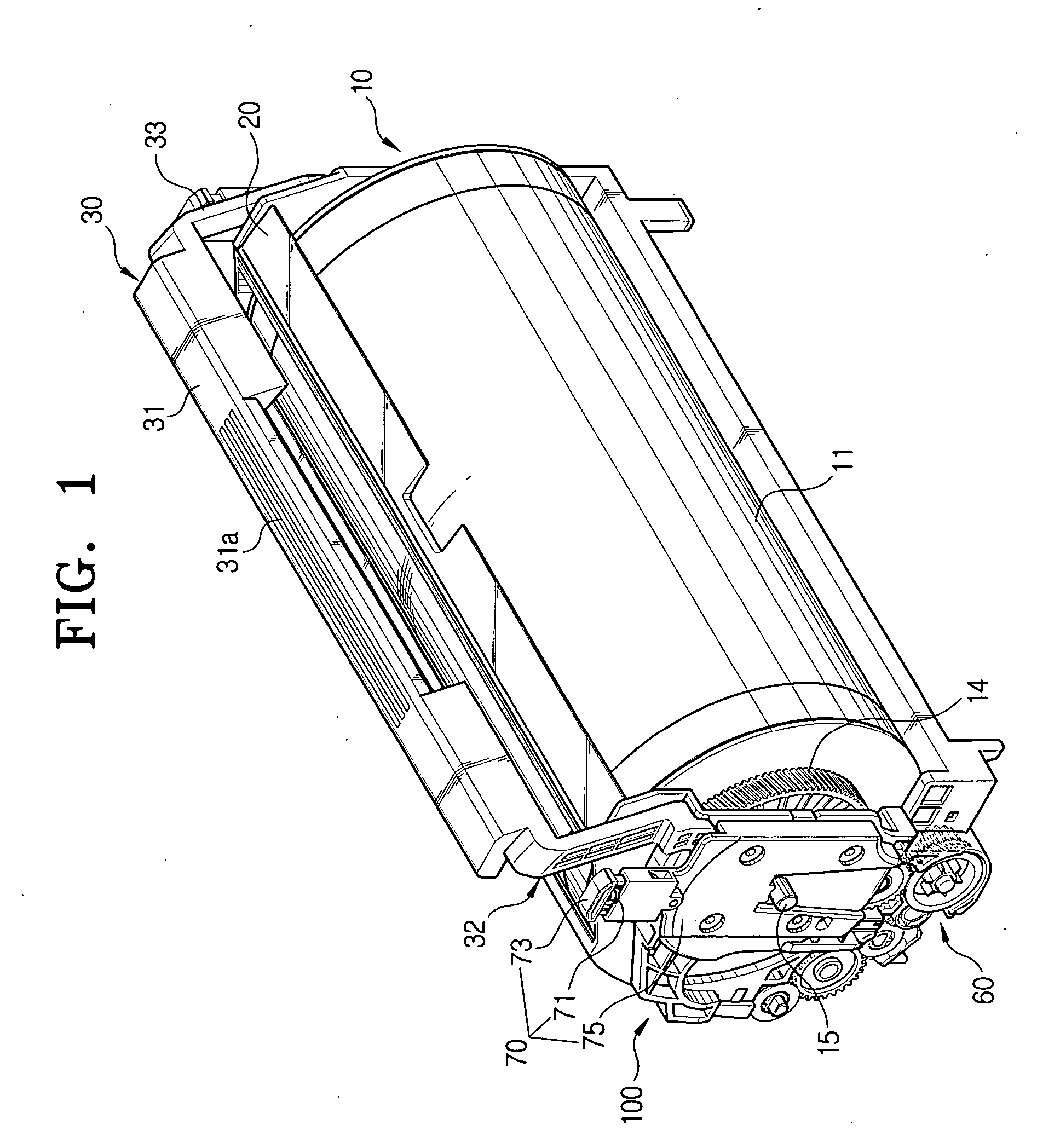
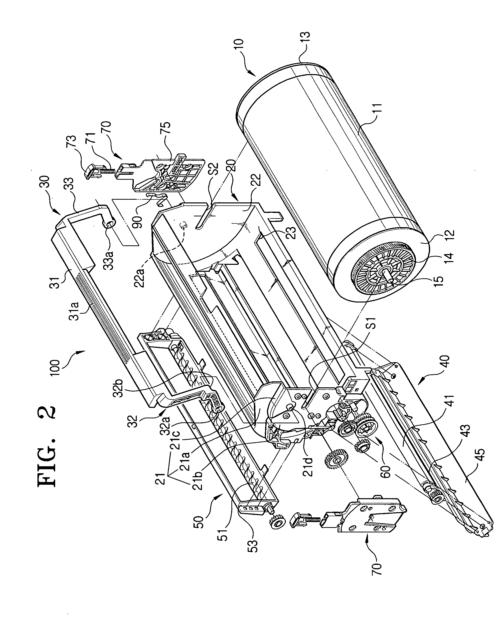
[0042] Reference will now be made in detail to the embodiments of the present invention, examples of which are illustrated in the accompanying drawings, wherein like reference numerals refer to the like elements throughout. The embodiments are described below in order to explain the present invention by referring to the figures. The matters defined in the description such as a detailed construction and elements are nothing but the ones provided to assist in a comprehensive understanding of the invention. Thus, it is apparent that the present invention can be carried out without those defined matters. Also, well-known functions or constructions are not described in detail since they would obscure the invention in unnecessary detail.

[0043]FIG. 1 is a perspective view of a photoreceptor unit 100 according to an embodiment of the present invention. FIG. 2 is an exploded perspective view of the photoreceptor unit 100. FIG. 3 is a partially exploded perspective view with parts broken awa...


PUM


Abstract

A photoreceptor unit includes a photoconductive drum assembly, a housing to enclose the photoconductive drum assembly to be rotatable therein, a handgrip rotatably formed on the housing, and a stopper to prevent the housing with the photoconductive drum assembly from becoming lopsided toward its preponderant side of the housing with respect to a center of rotation of the handgrip when the housing is lifted up by the handgrip.

Description

CROSS-REFERENCE TO RELATED APPLICATIONS [0001] This application claims the benefit of Korean Patent Application No. 2003-72073 filed Oct. 16, 2003, in the Korean Intellectual Property Office, the disclosure of which is incorporated herein by reference. BACKGROUND OF THE INVENTION [0002] 1. Field of the Invention [0003] The present invention relates to a photoreceptor unit to form an image to be transferred onto a transfer medium. [0004] 2. Description of the Related Art [0005] As is generally known in the art, a printing machine, such as a laser printer or a photocopier, comprises a photoreceptor unit for the development of images. [0006] A photoreceptor unit is valid during a limited period of time and is required to be replaced at the end of its life cycle in order to develop and produce clean images. For the facilitation of the replacement, a photoreceptor unit is generally modularized to be replaced as a whole with a new one. [0007] A modularized photoreceptor unit may include a...

Claims


Application Information

Patent Timeline
IPC IPC(8): G03G21/16G03G15/00G03G15/02G03G15/16G03G21/10G03G21/18
CPCG03G21/1828G03G2221/1846G03G21/1846G03G15/02
Inventor YOO, YONG-BAEKBAEK, CHUNG-GUK
Owner S PRINTING SOLUTION CO LTD
Learn More