
Method for collision avoidance and collision mitigation

a collision avoidance and collision technology, applied in the field of collision avoidance and collision mitigation, can solve the problems of not using, all prior art systems or methods are difficult to handle, and the driver shuts down the collision avoidance function, so as to avoid vehicle collisions

Inactive Publication Date: 2005-04-21
FORD GLOBAL TECH LLC
View PDF5 Cites 12 Cited by
  • Summary
  • Abstract
  • Description
  • Claims
  • Application Information

AI Technical Summary

Benefits of technology

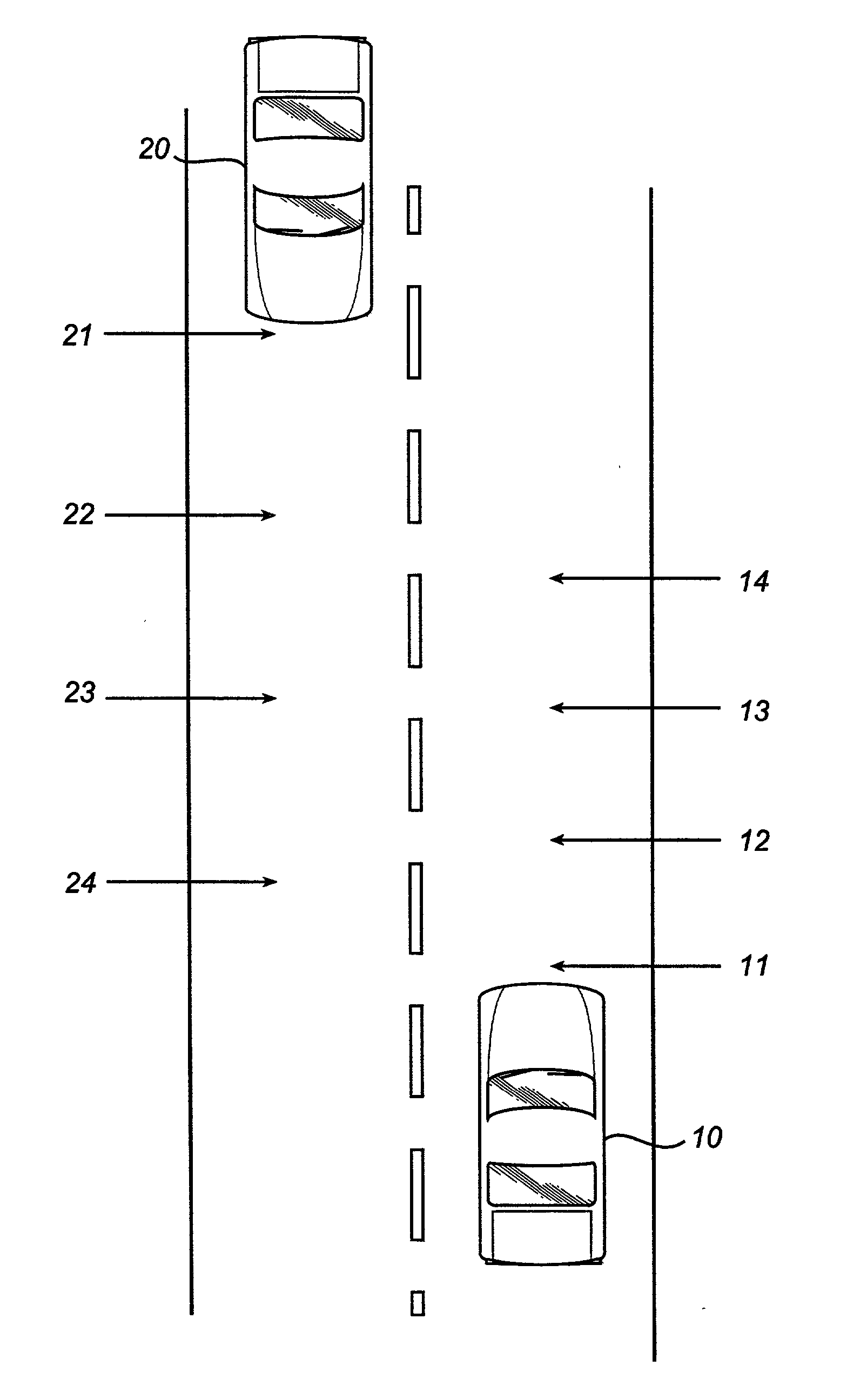
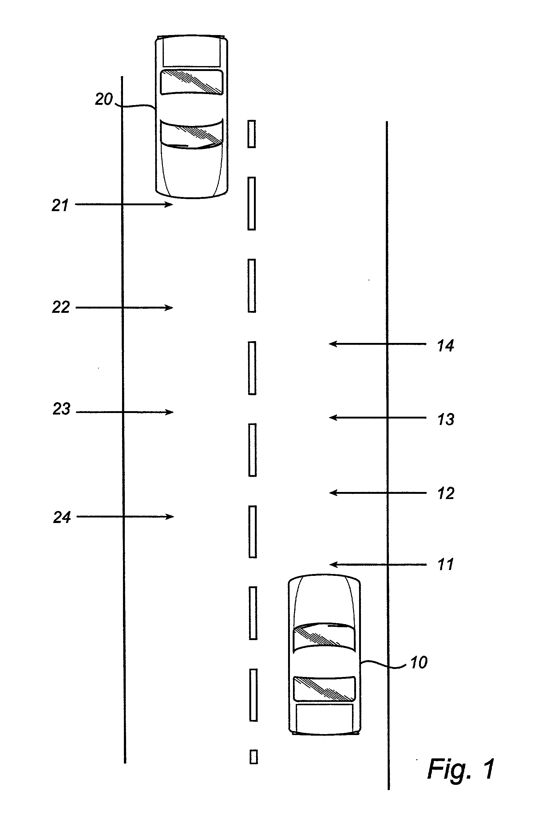
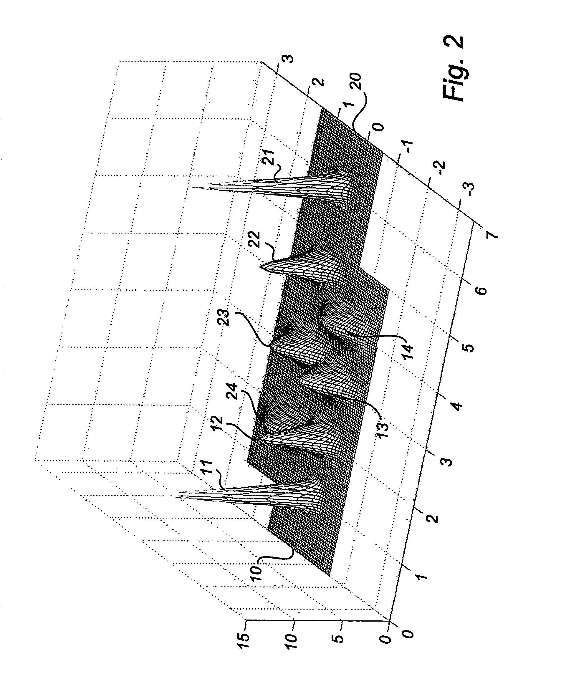
[0012] The foregoing and other advantages are provided by a method and apparatus for collision avoidance and collision mitigation. The present invention relates to a method for avoiding vehicle collisions and collision mitigation. The method comprises the steps of predicting the probability density function (11, 12, 13, 14) for the position of a vehicle at several future occasions and predicting the probability density function (21, 22, 23, 24) for at least one additional object at several future occasions. Further the method comprises the step of forming the joint probability density function for the relative positions of the vehicle and object at several future occasions and integrating over the area in which the vehicle and object are in physical conflict.

Problems solved by technology

All of the above described prior art collision avoidance systems and methods either are dependant of external signal transmitters, for example GPS satellite communication or communication between vehicles equipped with collision avoidance systems, or they result in giving alarm signals too frequently when implemented in an automobile.
All of the prior art systems or methods have difficulties handling situations like a vehicle meeting another vehicle traveling in the opposite direction on a two way road.
If a collision avoidance system or method were to give an alarm signal every time the vehicle equipped with such a system meets another vehicle, this would be a nuisance to the driver and could result in the driver shutting down the collision avoidance function and not using it at all.

Method used


Image

  • Method for collision avoidance and collision mitigation
  • Method for collision avoidance and collision mitigation
  • Method for collision avoidance and collision mitigation

Examples


Embodiment Construction

[0020] The method according to the invention will be explained with reference made to an example illustrated in the enclosed figures. The example is chosen in order to facilitate the reading and understanding of the method according to the present invention. Therefore, most of the diagrams in the figures show the probability density functions in one direction.

[0021]FIG. 1 illustrates a common situation with two vehicles meeting on a straight road. The vehicle equipped with the collision avoidance system is denoted 10 and the other vehicle is denoted 20. Throughout the example the probability density function has been calculated for both the vehicles at four future occasions (the same for both vehicles) The four future occasions are denoted 11, 12, 13 and 14, for the vehicle equipped with the collision avoidance system, with the same time interval between the future occasions. For the other vehicle the four future occasions are denoted 21, 22, 23 and 24. The occasion 11 for the firs...


PUM


Abstract

An adaptive cruise control system includes a forward-looking sensor generating a range signal corresponding to a distance between the host vehicle and a target vehicle. The forward-looking sensor also generates a range rate signal corresponding to a rate that the distance between the host vehicle and the target vehicle is changing. A controller is electrically coupled to the forward-looking sensor. The controller maintains a preset headway distance between the host vehicle and the target vehicle by adjusting the host vehicle velocity in response to the range signal and the range rate signal. The host vehicle may come to a full stop when the target vehicle is acquired below a predetermined velocity. If the target vehicle is acquired above the predetermined velocity, then a warning is given when braking is required.

Description

TECHNICAL FIELD [0001] The present invention relates to a method for avoiding collisions and collision mitigation involving vehicles and other objects. Specifically, the method is focused on predicting the probability density function for said vehicles and objects. BACKGROUND OF THE INVENTION [0002] Several methods have been developed for collision avoidance utilizing sensors to obtain values such as distance, speed and direction of objects and vehicles. [0003] U.S. Pat. No. 4,623,966 discloses an apparatus for collision avoidance for marine vessels. This apparatus comprises sensing means for providing signals representative of the positions and velocities of other vehicles relative to a first vehicle. These signals are used in a deterministic way to assess maneuvers of the first vehicle, which will avoid collision with the other vehicles. Collision danger is assessed through measures such as closest passing point, predicted point of collision and predicted areas of danger. [0004] R...

Claims


Application Information

Patent Timeline
Patent Type & Authority Applications(United States)
IPC IPC(8): B60T7/22G08G1/16
CPCB60T7/22B60W40/04G08G1/16B60W2550/20B60W2520/14G08G1/166B60W2554/00B60W2050/0052
Inventor TARABISHY, M. NABEELENGELMAN, GERALD H.LIND, HENRIKMODIGSSON, ALEXANDERTELLIS, LEVASSEURBOND, JOHN VINCENT III
Owner FORD GLOBAL TECH LLC
Learn More