

Air-conditioning system for motor vehicle
- Summary
- Abstract
- Description
- Claims
- Application Information
AI Technical Summary
Benefits of technology
Problems solved by technology
Method used
Image

Examples
first embodiment
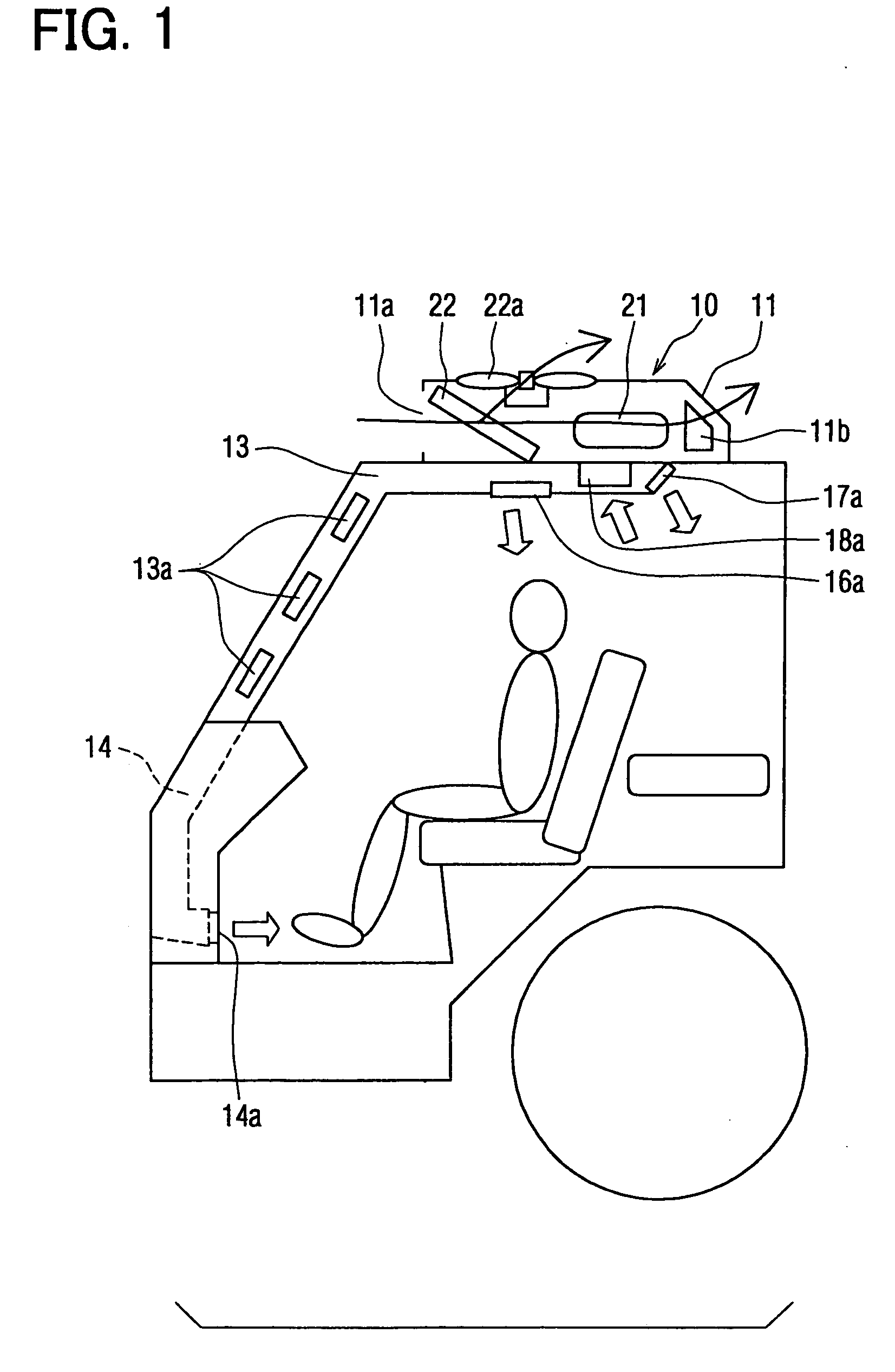
[0029] A first embodiment of the present invention will be explained with reference to FIGS. 1 to 6.
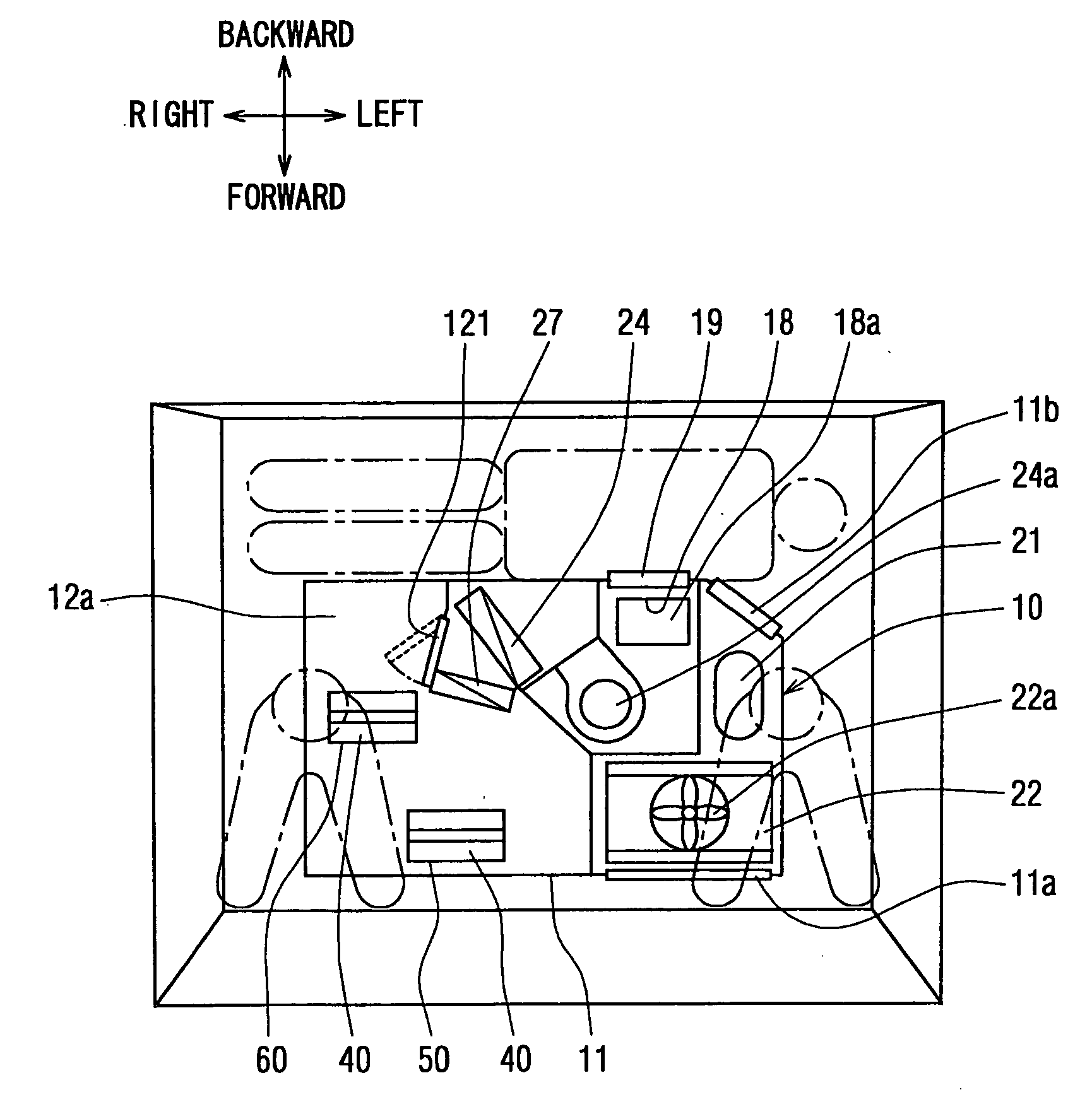
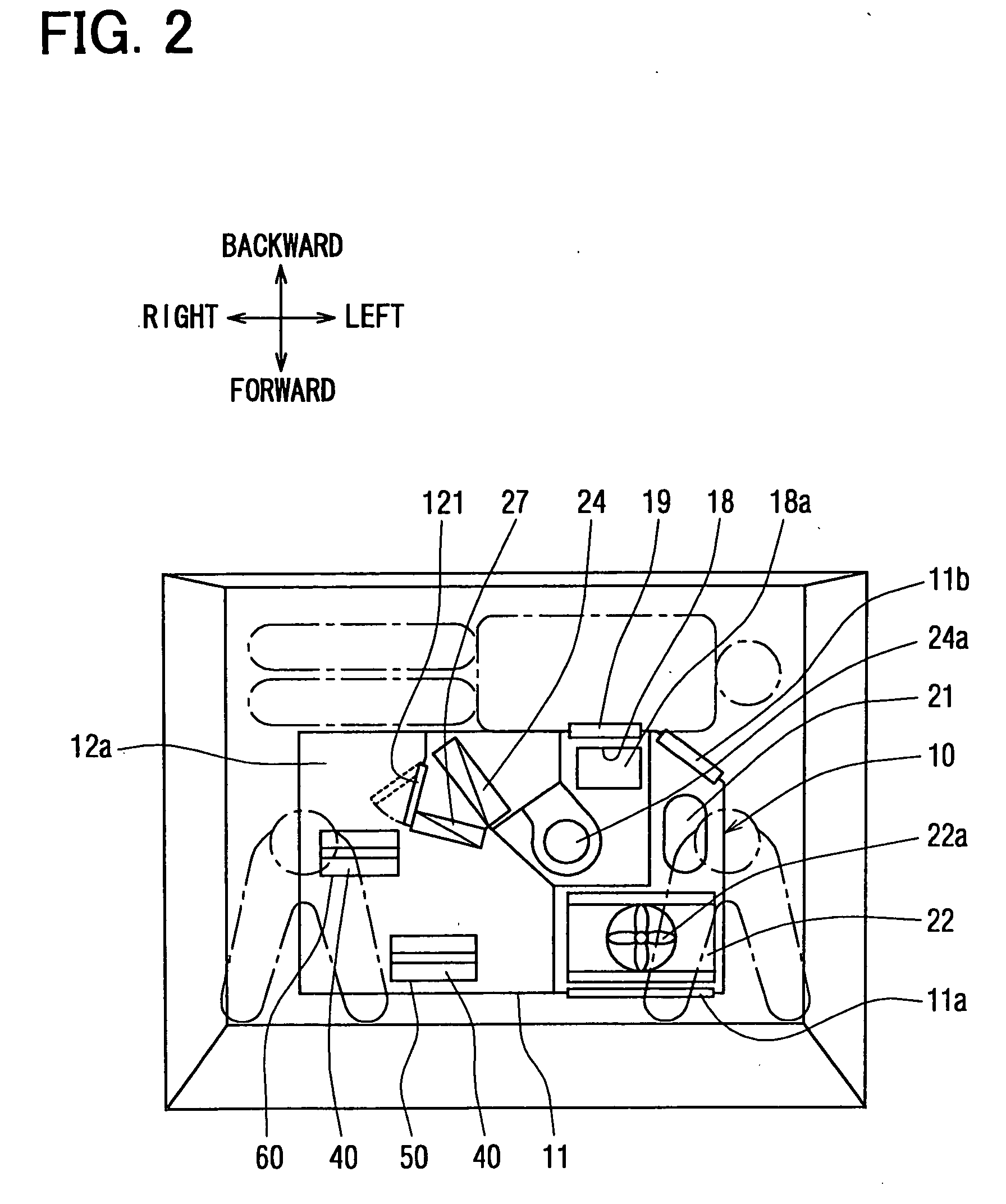
[0030] An air-conditioning system for a motor vehicle according to the first embodiment of the present invention comprises, as shown in FIG. 1, an air-conditioning unit 10 mounted on a roof of the motor vehicle, multiple blower openings 13a to 17a, 16e (FIGS. 5 and 6) for blowing out conditioned air into a passenger compartment in accordance with respective operational modes, multiple blower ducts 13 to 17 (FIGS. 5 and 6) for sending the conditioned air from the air-conditioning unit 10 to the respective blower openings 13a to 17a, and 16e, and an air suction opening 18a for sucking in the air from the passenger compartment.
[0031] The air-conditioning unit 10 has a refrigerating cycle device 20 (FIG. 4) in its unit case 11, which comprises a compressor 21, a condenser 22 and so on. The unit case 11 is formed with duct openings 50 and 60, to which the multiple blower ducts 13 to 17 a...
second embodiment
[0089] A second embodiment of the present invention will be explained with reference to FIGS. 7 and 8, which differs from the first embodiment in the structure of the foot blower duct 14.
[0090] As shown in FIG. 7, the foot blower duct 14 comprises a horizontally and longitudinally extending duct portion 14b (a first duct portion) arranged at an inner surface of the vehicle roof, a vertically extending duct portion 14c (a second duct portion) provided at a backward side of a passenger compartment and communicated at its one end with the first duct portion 14e, a horizontally and longitudinally extending duct portion 14f (a third duct portion) provided at a floor beneath a center console 3 and communicated at its one end with the other end of the second duct portion 14c, and a pair of forked duct portions 14g (a fourth duct portion) extending from the other end of the third duct portion 14f toward the front side of the passenger compartment and terminating at the vicinity of the pass...
third embodiment
[0094] In the first embodiment, the face blower openings 16a are formed in the horizontally and longitudinally extending duct portions 16c and the nap-taking blower openings 17a are formed in the horizontally and laterally extending duct portion 16b, as shown in FIG. 6. In the third embodiment, shown in FIG. 9, however, a nap-taking blower duct 17 is provided in the place of the face blower duct 16 of the first embodiment (FIG. 6) and the nap-taking blower openings 17a are formed in the nap-taking blower duct 17. The face blower openings 16a are formed in the horizontally and longitudinally extending duct portions 15c, wherein the side defroster blower openings 15a are formed, as in the same manner to the first embodiment (FIG. 6), directing toward the side windshields of the vehicle, while the face blower openings 16a are directed toward the upper body of the passengers.
[0095] As in the same manner to the first embodiment, the air inlet opening 15d of the side defroster blower duc...
PUM
 Abstract
Description
Claims
Application Information