Viscous damper

a viscous damper and damper technology, applied in the direction of fluid couplings, couplings, rotary clutches, etc., can solve the problems of inability to achieve a sufficient suppression of vibration and noise in the viscous damper or the power transmission device, and the occurrence of resonance phenomena by the torsion spring or the elastic member as the first damper means is unavoidable, so as to achieve the effect of viscous damper, reducing gear noise, and avoiding gear damage gear noise nois

Active Publication Date: 2005-04-28
HONDA MOTOR CO LTD
View PDF8 Cites 4 Cited by
  • Summary
  • Abstract
  • Description
  • Claims
  • Application Information

AI Technical Summary

Benefits of technology

[0016] Further, since the load acting on the gearing between the crankshaft and the viscous damper is reduced, damages to the gearing can be avoided, and the gear noise can be reduced. As a result, in addition to the vibration and noise damping and absorbing effects, the power transmission device for driving accessories which affords a stable power transmission with a relatively simple structure can be provided.
[0017] According to a fourth aspect of the invention, the housing is provided with a weight section which is an annular protrusion axially extending near

Problems solved by technology

In a viscous damper of such a construction, an occurrence of resonance phenomena by the torsion spring or the elastic member as the first damper means is unavoidable.
The occurrence of resonance phenomena causes new vibration and noise in the viscous damper or the power transmission device using the viscous damper, resulting in a failure to accomplish a sufficient suppres

Method used


Image

  • Viscous damper
  • Viscous damper
  • Viscous damper

Examples


Embodiment Construction

[0027] A viscous damper is suitably implemented in a power transmission device for driving the alternator by the crankshaft of an internal combustion engine in a motorcycle.

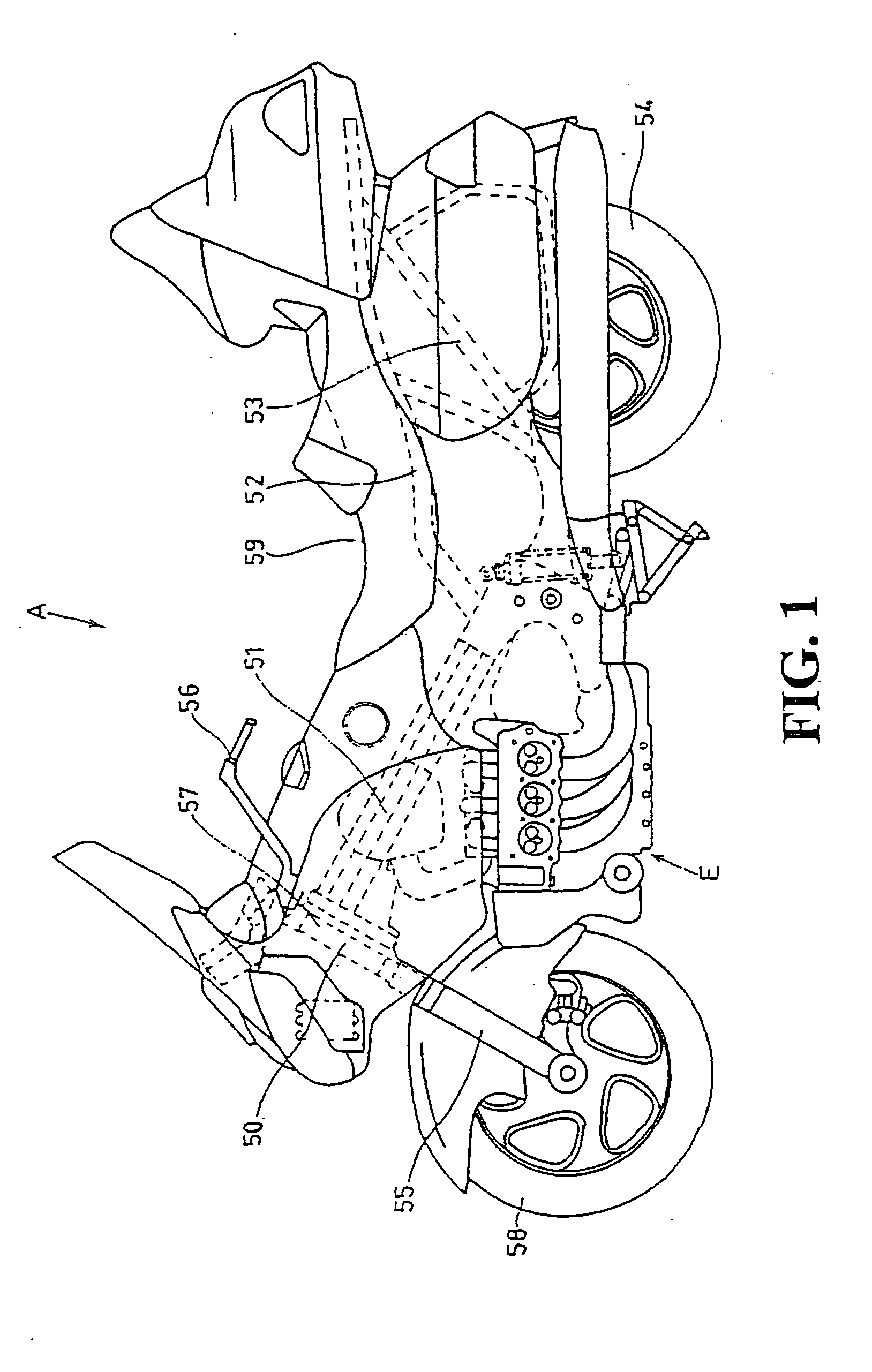
[0028] Embodiments according to the present invention will be described with reference to FIG. 1 through FIGS. 6(a) and (b). First, a motorcycle A comprising a power transmission device for driving accessories in which a viscous damper according to the present invention is used and an internal combustion engine E mounted on the motorcycle A will be outlined.

[0029] As shown in FIG. 1, the motorcycle according to the present invention comprises a head pipe 50 and a main frame 51 which is connected to the head pipe 50 at one end and extends downwardly at a slanting angle from the head pipe 50. Near the rear end of the main frame 51, a seat rail 52 extending therefrom slightly upwardly and rearwardly is attached. Further, at the rear end of the main frame 51, a back stay 53 extends therefrom upwardly and rearwardly...


PUM


Abstract

A viscous damper for driving accessories by a crankshaft though a viscous coupler of the viscous damper. The rotational driving force of the crankshaft is transmitted to the viscous damper hub through the meshing of a large diameter gear and a driven gear, the viscous damper forming a unit with the driven gear. The rotational driving force is further transmitted to a viscous damper housing through the hub and the viscous coupling means, i.e., the viscous coupling means comprising a number of plates which are movable relative to each other in a space filled with silicon oil. The rotational driving force, which is transmitted to the housing and is dampened in torque changes by the function of the coupling means, is transmitted to a rotor shaft of an alternator to smoothly rotate the alternator rotor. A smooth performance in driving the accessories is ensured by the viscous damper having the viscous coupling.

Description

CROSS-REFERENCE TO RELATED APPLICATION [0001] The present application is related to Japanese Patent Application No. 2003-333326, filed on Sep. 25, 2003, the entire contents of which are hereby incorporated by reference. BACKGROUND OF THE INVENTION [0002] 1. Field of the Invention [0003] The present invention relates to a viscous damper, and more particularly to a viscous damper which is used as a damper in a power transmission device that drives accessories such as an alternator and the like by means of a gearing directly coupled with a crankshaft through the damper. [0004] 2. Description of Background Art [0005] For a power transmission device in conventional vehicles, a power transmission device using a viscous damper has been well known. An example is a power transmission device having a construction in which the rotational driving force of a first flywheel directly connected to a crankshaft is transmitted to a second flywheel via a torsion spring and a viscous damper, and the ro...

Claims


Application Information

Patent Timeline
IPC IPC(8): F16C3/06F16D3/12F16D3/80F02B77/00F16D33/00F16F15/121F16F15/131F16F15/16F16F15/167F16F15/173
CPCF16F15/16
Inventor OSADA, KUNIHIRONAKATSUKA, MASAHIKOSONOBATA, AKIRA
Owner HONDA MOTOR CO LTD
Why Eureka
Try Eureka