Tactile touch-sensing system

a touch sensor and tactile technology, applied in instruments, cathode-ray tube indicators, computing, etc., can solve the problems of inability to provide tactile feedback, inacceptable touch sensor systems etc., and achieve the effect of no tactile feedback, cost and complication

Inactive Publication Date: 2005-04-28
3M INNOVATIVE PROPERTIES CO
View PDF11 Cites 310 Cited by
  • Summary
  • Abstract
  • Description
  • Claims
  • Application Information

AI Technical Summary

Benefits of technology

[0007] In response to being pressed, the tactile button is configured to provide tactile feedback to the user and to activate the touch-generating pad. The touch-generating pad, when activated by the tactile button, causes a detectable touch on the touch sensor. In this way, tactile button activation can be detected by the touch sensor, as opposed to detection only by separate circuitry associated with the tactile button. In some designs, it may be desirable to be able to detect touch pad activation by the touch sensor as well as by circuitry dedicated to the touch pad. This may provide additional signals that can be used for calibration, diagnostics, redundancy, or to access additional functionalities.
[0008] The present invention provides a simple way to configure a touch-sensing system to provide users with tactile feedback. Conventional touch-sensing systems typically have a smooth, one-piece surface for receiving touches and essentially provide no tactile feedback. The tactile touch-sensing system of the present invention provides tactile feedback to the user without the cost and complication associated with adding a conventional control circuit with buttons and switches to an ordinary touch-sensing system.

Problems solved by technology

Control mechanisms in a touch-sensing system may be consolidated by presenting input selections to the user in multiple layers of menus, saving space and manufacturing cost.
While touch-sensing systems are gradually replacing conventional input systems in many applications, there are still some applications where touch-sensing systems are not viewed as acceptable.
One criticism of touch-sensing systems is their failure to provide tactile feedback.
However, if an electronic device is used in an environment where ambient noise is intense or lighting is limited, auditory or visual feedback may not be effective.

Method used


Image

  • Tactile touch-sensing system
  • Tactile touch-sensing system
  • Tactile touch-sensing system

Examples


Embodiment Construction

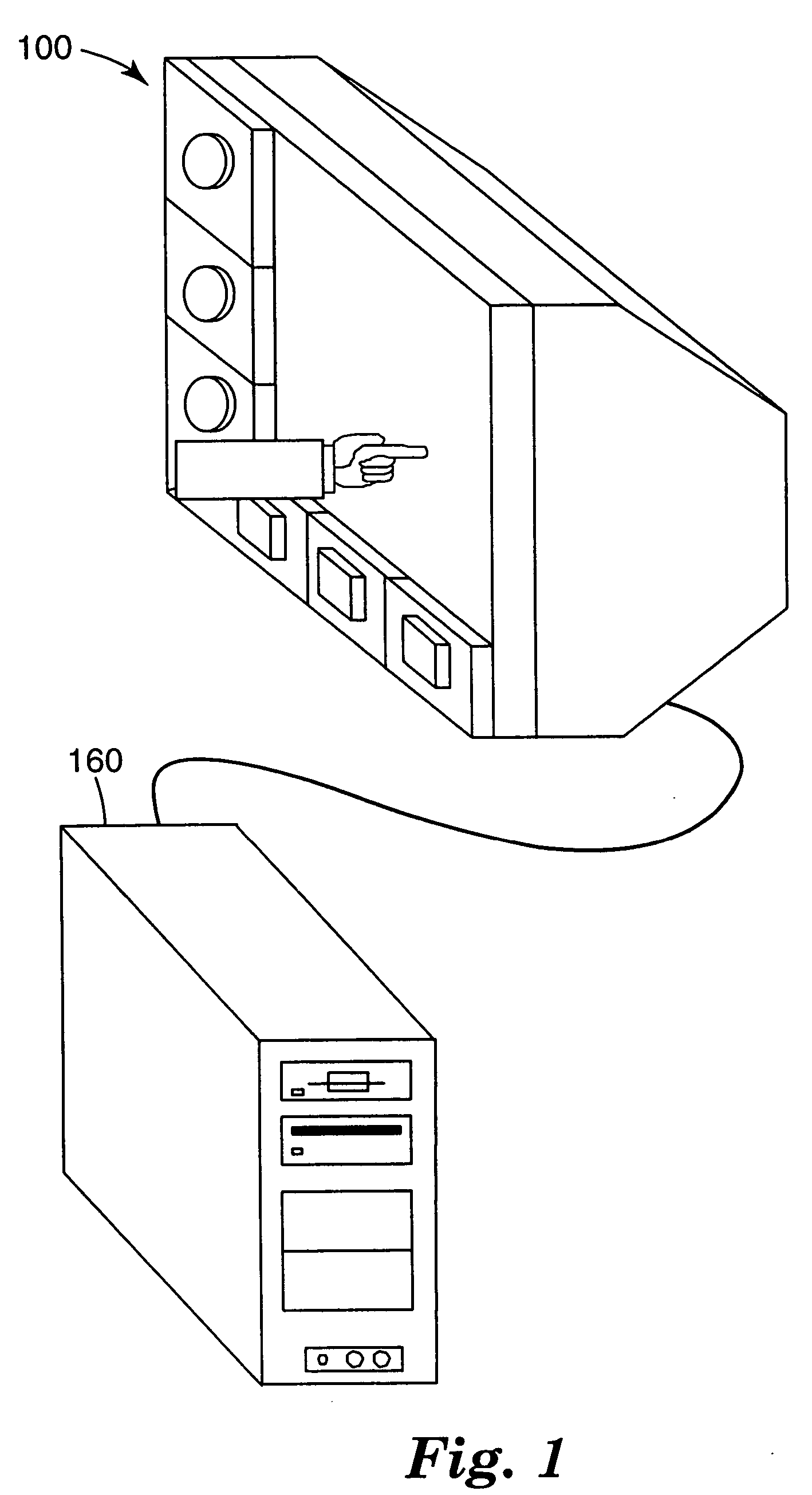
[0016]FIG. 1 is a schematic representation of one implementation of the present invention, showing an exemplary tactile touch-sensing system 100. Tactile touch-sensing system 100 enables a user to enter inputs to an electronic device, such as computer 160, and provides the user with tactile feedback. Typically, tactile touch-sensing system 100 enables computer 160 to display information for interacting with the user.

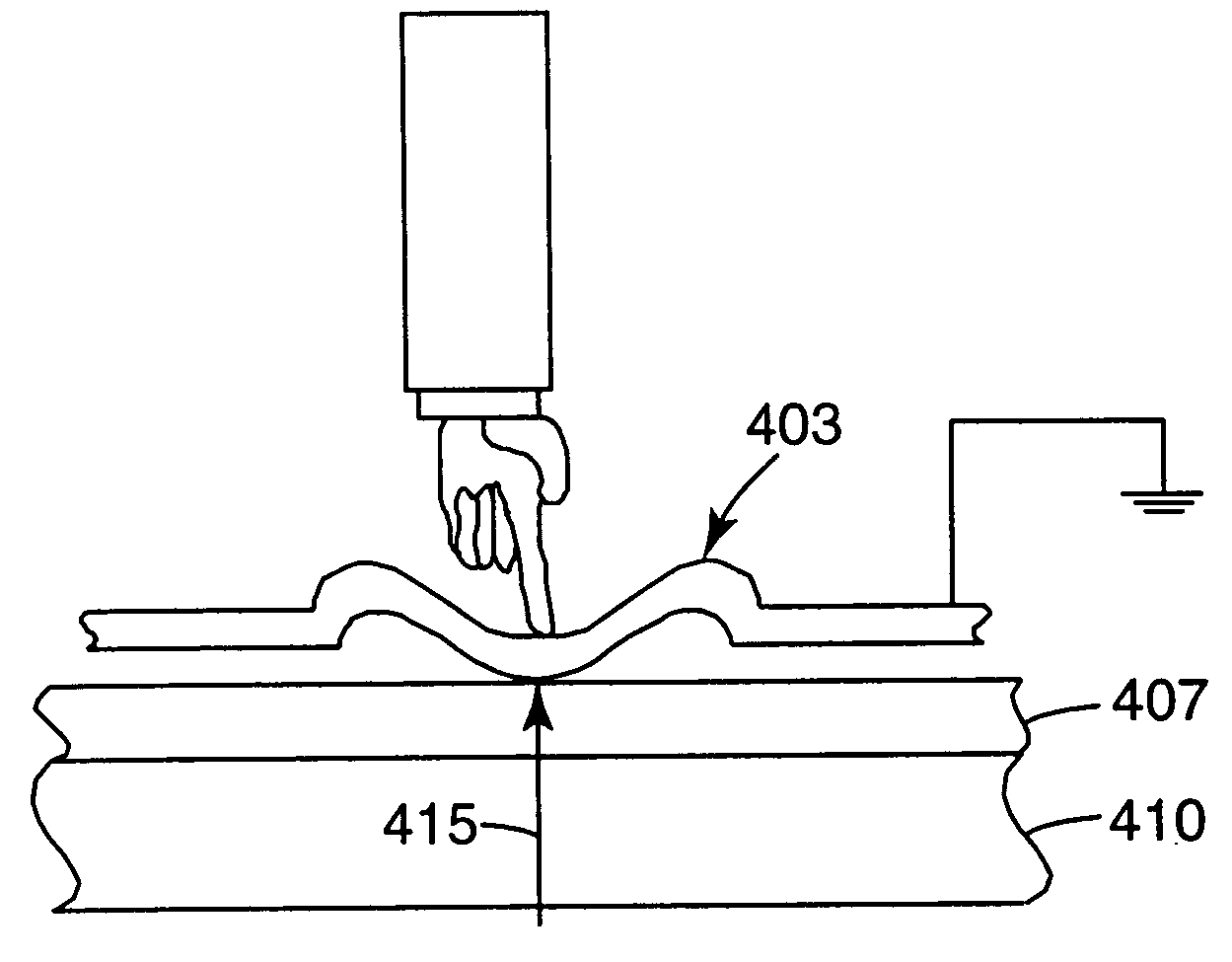
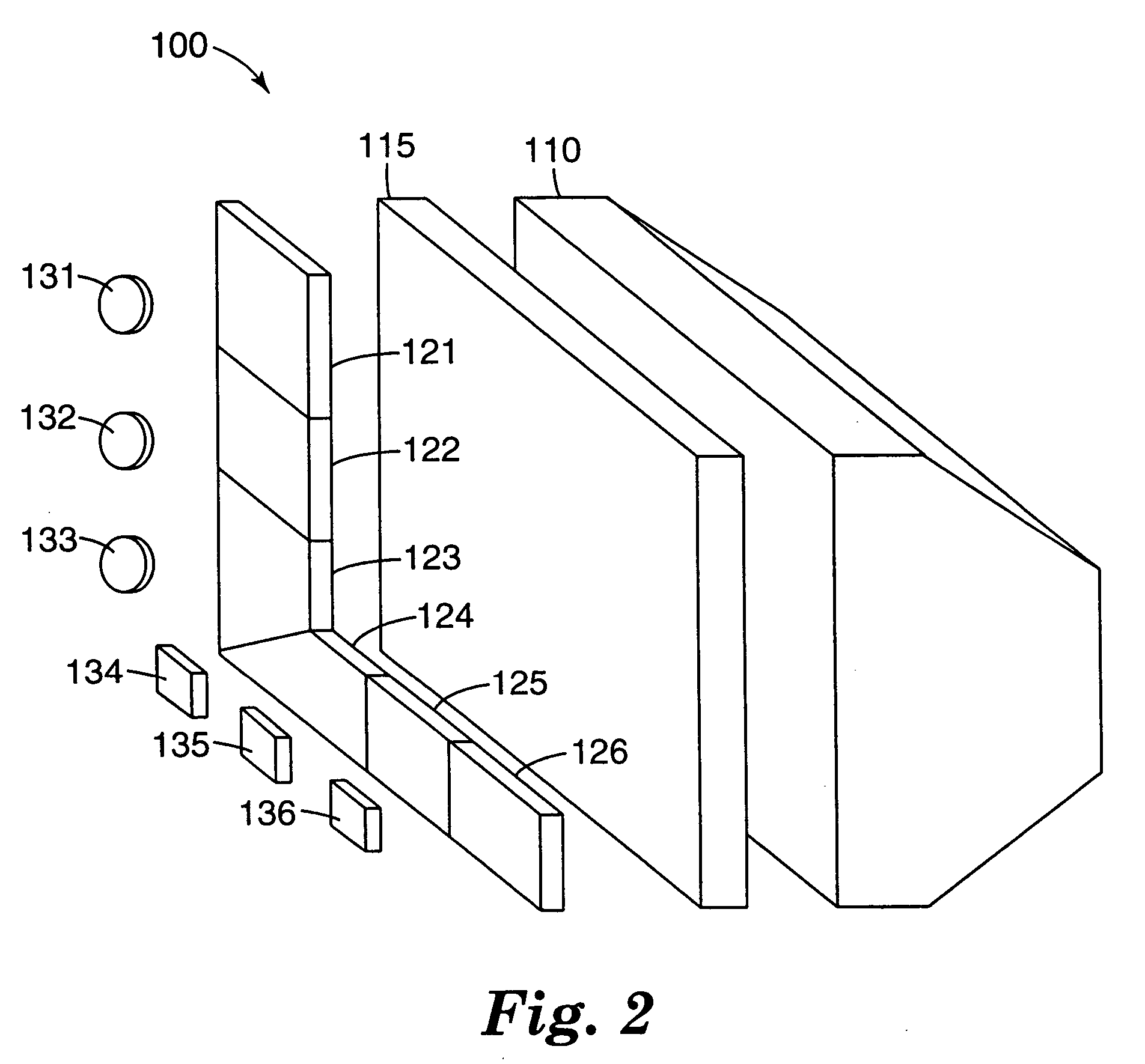
[0017] Tactile touch-sensing system 100 may include many components, which will be discussed in more detailed in conjunction with FIG. 2. Typically, tactile touch-sensing system 100 includes a touch sensor configured to generate signals in response to a touch on the touch sensor. For tactile touch-sensing system 100, a user can touch the touch sensor directly or indirectly through a touch-generating pad, which will be discussed in detail in conjunction with FIG. 2. Tactile touch-sensing system 100 may also include a control circuit that is configured to process the sign...


PUM


Abstract

A tactile touch-sensing system that includes a touch sensor, touch-generating pads, and tactile buttons. The touch sensor is configured to produce an electrical signal in response to a touch. The touch-generating pads cover at least a part of the touch sensor and are configured not to cause a touch on the touch sensor before they are activated. A user can activate a touch-generating pad by pressing a tactile button associated with the touch-generating pad. In response to being pressed, the tactile button is configured to provide tactile feedback to the user. The touch-generating pad, when activated by the tactile button, causes a touch on the touch sensor.

Description

BACKGROUND [0001] As computers and other electronic devices become more ubiquitous, touch-sensing systems are becoming more prevalent as a means for inputting data. For example, touch-sensing systems may now be found in workshops, warehouses, manufacturing facilities, restaurants, on hand-held personal digital assistants, automatic teller machines, casino game-machines, and the like. [0002] A touch-sensing system often includes a touch sensor and a display device. The display device usually includes a display screen for presenting graphical information to users. A touch sensor ordinarily includes a transparent sensing circuit placed on top of the display screen for sensing the position of a touch on the screen. Touch-sensitive displays are often used as a replacement for conventional hardware input devices. For example, the display screen may be used to illustrate icons that look like buttons. A user may touch the screen in the location of the icon, resulting in a signal correspondi...

Claims


Application Information

Patent Timeline
Patent Type & Authority Applications(United States)
IPC IPC(8): G06F3/02G06F3/048G09G5/00
CPCG06F2203/04809G06F3/04886G06F3/016G06F3/02
Inventor MULLIGAN, ROGER C.
Owner 3M INNOVATIVE PROPERTIES CO
Why Eureka
Try Eureka