Electronically Based Control Valve with Feedback to a Building Management System (BMS)

a control valve and electronic technology, applied in the field of heat transfer, can solve the problems of circuits with the most need not being constant, circuits becoming the most demanding, etc., and achieve the effects of low cost, low cost, and low cos

Inactive Publication Date: 2008-03-06
IMI HYDRONIC ENG
View PDF28 Cites 30 Cited by
  • Summary
  • Abstract
  • Description
  • Claims
  • Application Information

AI Technical Summary

Benefits of technology

[0006]Certain embodiments of the invention may provide numerous technical advantages. For example, certain embodiments may allow the individual terminal to still regulate its return water temperature even if communication to the building management system failed. Additionally, certain embodiments may allow the building production equipment to be operated in an efficient manner without undue cost or complication. Still further, certain embodiments may allow a system to be more robust since the failure of communication with a single valve would only occasionally degrade the efficiency of the system; the remaining valves would typically provide enough information. Yet another advantage of certain embodiments may be the ability to use low cost self-acting valves while still giving the central building management system all the information and control needed for efficient system operation. A further advantage of certain embodiments might be the ability to remotely detect a malfunction of one of the valves.

Problems solved by technology

The disadvantage to this approach is that the circuit with the greatest need does not remain constant.
As the total flow in the distribution system decreases and the pressure difference between the risers in various locations equalizes, such circuits would become the most demanding.

Method used


Image

  • Electronically Based Control Valve with Feedback to a Building Management System (BMS)
  • Electronically Based Control Valve with Feedback to a Building Management System (BMS)
  • Electronically Based Control Valve with Feedback to a Building Management System (BMS)

Examples


Embodiment Construction

[0014]It should be understood at the outset that although example embodiments of the present invention are illustrated below, the present invention may be implemented using any number of techniques, whether currently known or in existence. The present invention should in no way be limited to the example embodiments, drawings, and techniques illustrated below, including the embodiments and implementation illustrated and described herein. Additionally, the drawings are not necessarily drawn to scale.

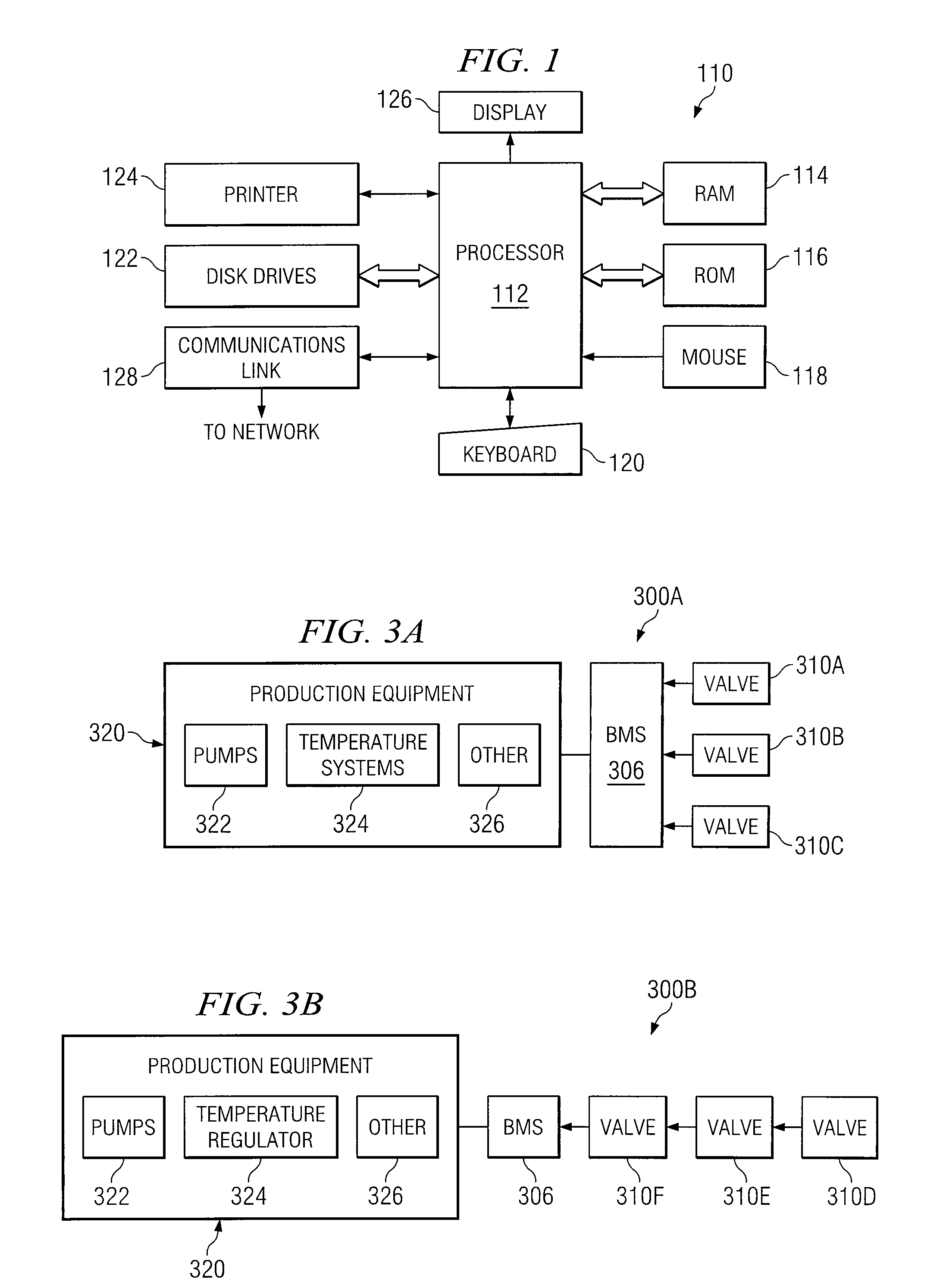
[0015]FIG. 1 shows an embodiment of a general purpose computer 110 that may be used in connection with one or more pieces of software and / or hardware employed by other embodiments of the invention. General purpose computer 110 may be adapted to execute any of the well-known OS2, UNIX, Mac-OS, Linux, and Windows Operating Systems or other operating systems. The general purpose computer 110 in the embodiment of FIG. 1 comprises a processor 112, a random access memory (RAM) 114, a read only m...


PUM


Abstract

According to one embodiment of the invention, a method for regulating temperature in a system comprises receiving, at a building management system, information concerning a degree of opening of a plurality of control valves. Each of the plurality of control valves is associated with at least one terminal that is in communication with a supply header line of a system, and is operable to open or close according to its own logic based on the demand of the associated terminal or terminals. A determination is made, based on the degree of opening of the plurality of control valves, as to whether changes need to be made to the operating parameters of production equipment of the system. The changes to the production equipment operation of the system are operable to change at least one parameter of a fluid being supplied to the supply header line of the system. An initiation of changes is made if it is determined that the change needs to be made. The changes in the production equipment yield a difference in the at least one parameter of the fluid.

Description

CROSS-REFERENCE TO RELATED APPLICATIONS[0001]Pursuant to 35 U.S.C. § 119 (e), this application claims priority from U.S. Provisional Patent Application Ser. No. 60 / 824,400, entitled ELECTRONICALLY BASED CONTROL VALVE WITH FEEDBACK TO A BUILDING MANAGEMENT SYSTEM (BMS), filed Sep. 1, 2006.TECHNICAL FIELD OF THE INVENTION[0002]This invention relates generally to the field of heat transfer and, more particularly, to an electronically based control valve with feedback to a building management system (BMS).BACKGROUND OF THE INVENTION[0003]A variety of different heat transfer systems use water or other fluids to transfer heat or thermal energy between one or more production units and one or more loads. Such systems are often referred to as hydronic systems.[0004]Many such systems employ variable pumping in which the speed of the pumps or number of active pumps is varied to maintain a constant pressure cross some terminal, sometimes referred to as the “index circuit.” The logic of choosing...

Claims


Application Information

Patent Timeline
Patent Type & Authority Applications(United States)
IPC IPC(8): F25B41/04F24F11/76
CPCF24D19/1015F24F11/06F24F3/06F24F11/83Y02P80/10F24F11/84
Inventor TRANTHAM, JOHN M.
Owner IMI HYDRONIC ENG
Why Eureka
Try Eureka