
Perficardial pacing lead placement device and method

a technology of perficardial pacing and lead placement, which is applied in the field of perficardial pacing lead placement devices and methods, can solve problems such as inability to readily address shortcomings

Inactive Publication Date: 2005-05-12
GRABEK JAMES R +1
View PDF15 Cites 107 Cited by
  • Summary
  • Abstract
  • Description
  • Claims
  • Application Information

AI Technical Summary

Problems solved by technology

Although transvenous leads are widely accepted for both pacing and defibrillation therapy, they still possess shortcomings which cannot be readily addressed by vascular access leads.

Method used


Image

  • Perficardial pacing lead placement device and method
  • Perficardial pacing lead placement device and method

Examples


Embodiment Construction

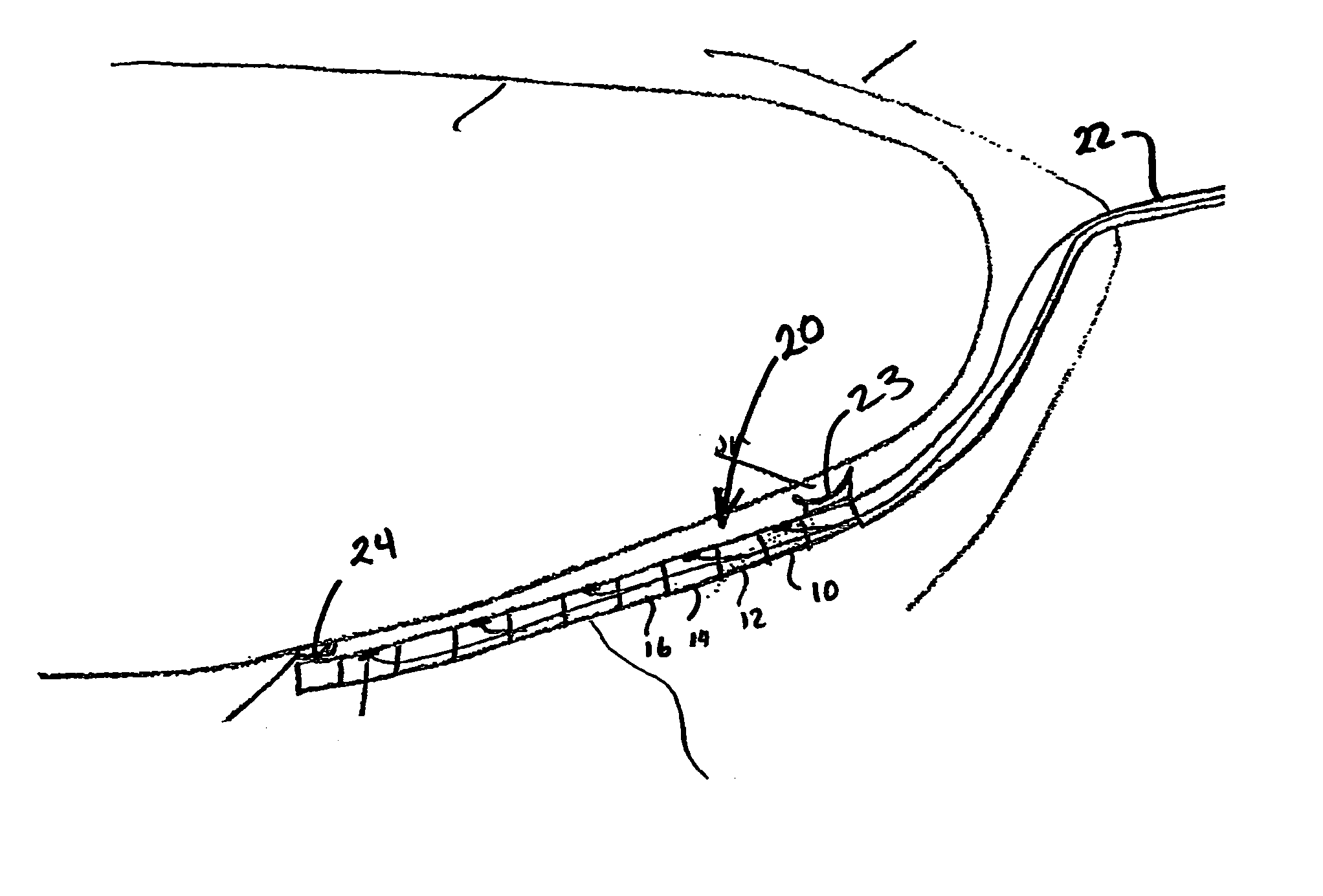
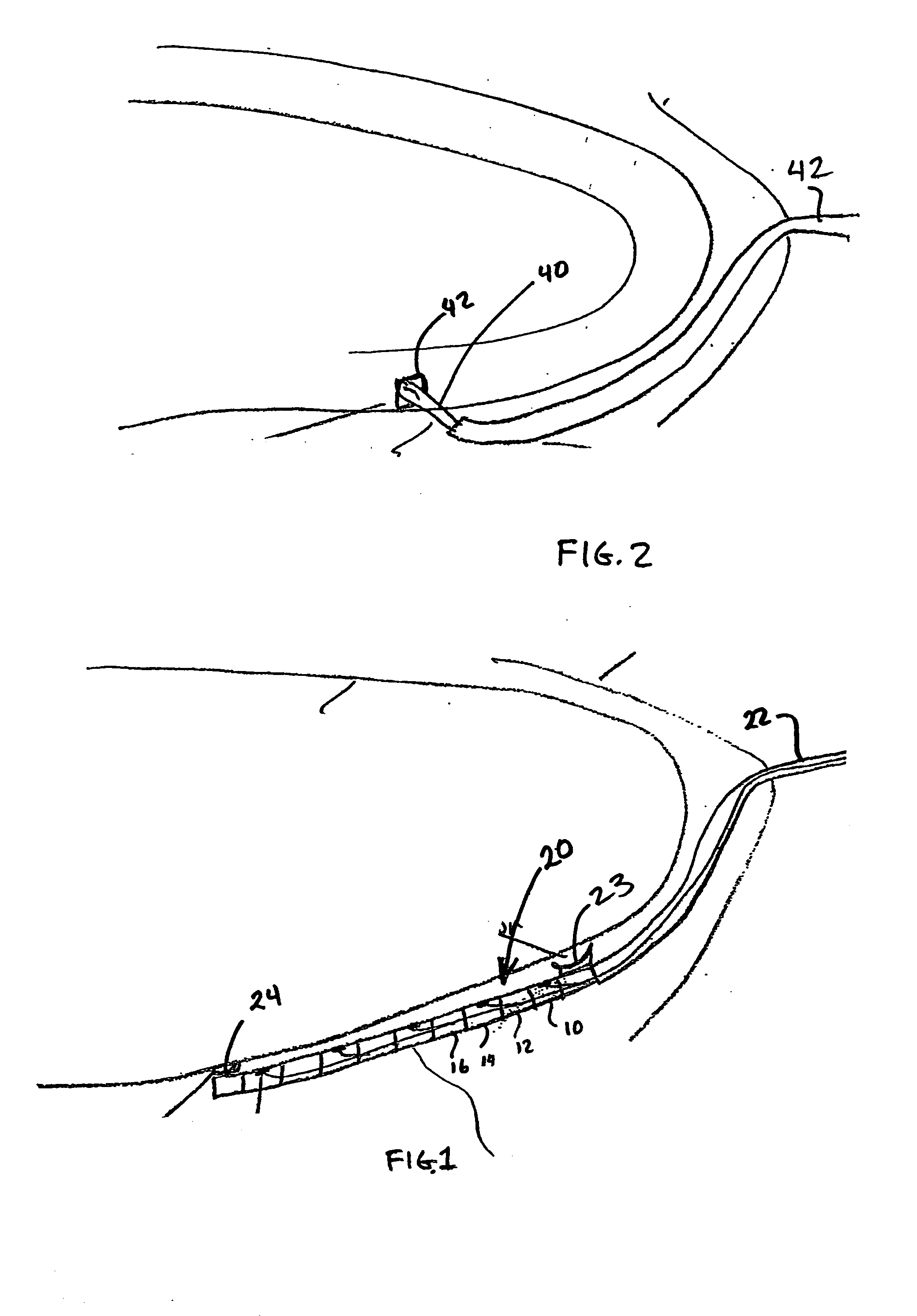
[0010]FIG. 1 shows a multiple link temporary pacing lead with electrode segments such as 10 and 14 separated by articulated insulators such as 12 and 16. Each electrode can be used to test the pacing parameters at the location associated with the electrode. It is desirable to determine the optimal pacing site especially for biventricular pacing. The articulated catheter 20 can be delivered to the posterior side of the heart and the right and left ventricle can each be accessed and paced. The distal anchor 24 can be a mechanical barb or a suction device to temporally fix the lead into position while the heart is tested. The lead may be stabilized in place with an optional proximal anchor 23 as well.

[0011]FIG. 2 shows a pacing lead with a barbed anchor that can be rotated in to attachment to the heart surface after placement on the posterior surface of the heart.

[0012] Taken as a system the catheter 20 of FIG. 1 can be used to explore and select the optimal pacing site. The pericard...


PUM


Abstract

The present invention relates to a method and apparatus for pacing the ventricle of a patient's heart through the pericardial space, including an epicardial lead and a method for placement of the lead.

Description

CROSS REFERENCE TO RELATED APPLICATION [0001] The present application is a Continuation-In-Part of U.S. patent application Ser. No. 09 / 565,059 filed May 3, 2000 which is co-pending with the present application, and which is incorporated by reference in its entirety. The present application claims the benefit of provisional application 60 / 421,541 filed Oct. 25, 2002 which is incorporated by reference in its entirety.BACKGROUND OF THE INVENTION [0002] The earliest pacemakers relied on an implanted lead system which was coupled to the epicardial surface of the heart. The electrodes were typically in the form of exposed metal coils which were sutured into stab wounds made on the epicardial surface of the ventricle. Surgical access to this site was through the chest and required breaking the sternum. [0003] Pacing as a therapy was adopted more widely with the introduction of a transvenous lead system which permitted the physician to place stimulation electrodes in the heart without the n...

Claims


Application Information

Patent Timeline
Patent Type & Authority Applications(United States)
IPC IPC(8): A61B18/14
CPCA61B2018/00351A61B18/1492
Inventor GRABEK, JAMES R.HOEY, MICHAEL
Owner GRABEK JAMES R
Learn More