Shoe sole having heel cushioning member

Inactive Publication Date: 2005-05-19
YEN CHAO HSIUNG
View PDF7 Cites 53 Cited by
  • Summary
  • Abstract
  • Description
  • Claims
  • Application Information

AI Technical Summary

Benefits of technology

[0007] The primary objective of the present invention is to provide a shoe sole including a resilient cushioning device for attaching to the

Problems solved by technology

However, the bladders or the air chambers formed in the shoe soles m

Method used


Image

  • Shoe sole having heel cushioning member
  • Shoe sole having heel cushioning member
  • Shoe sole having heel cushioning member

Examples


Example

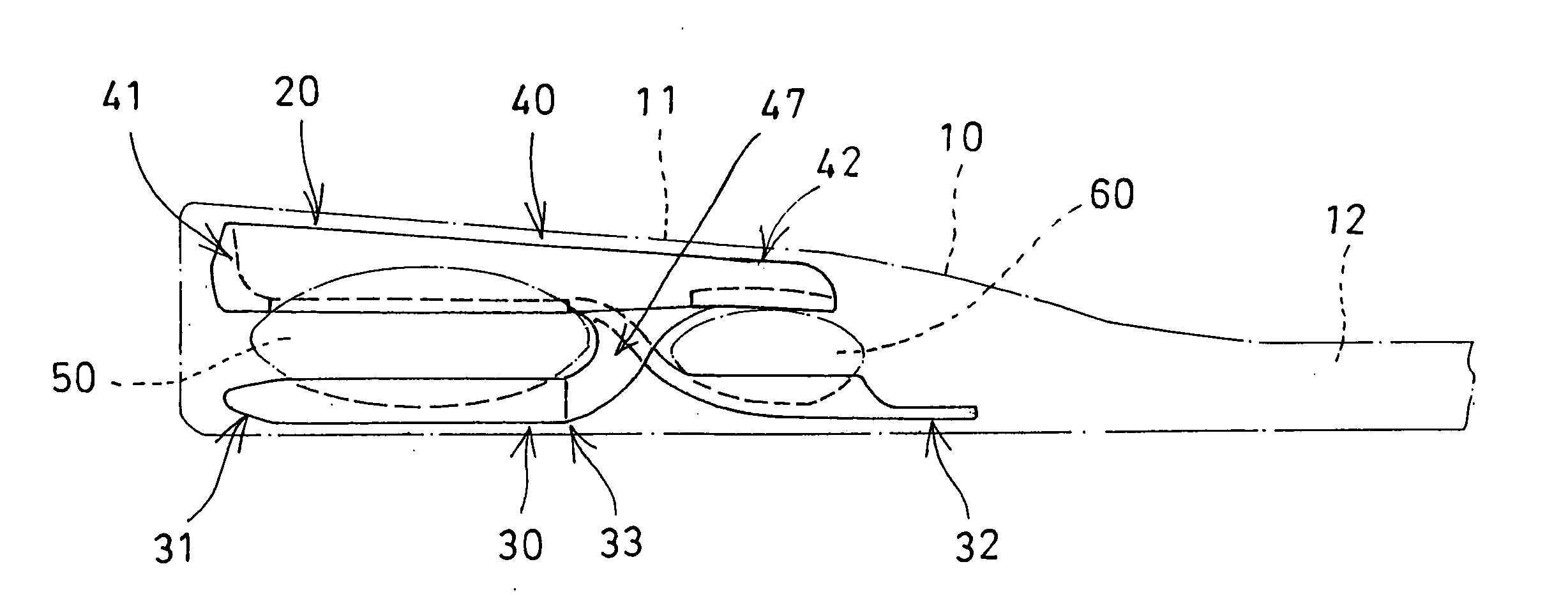
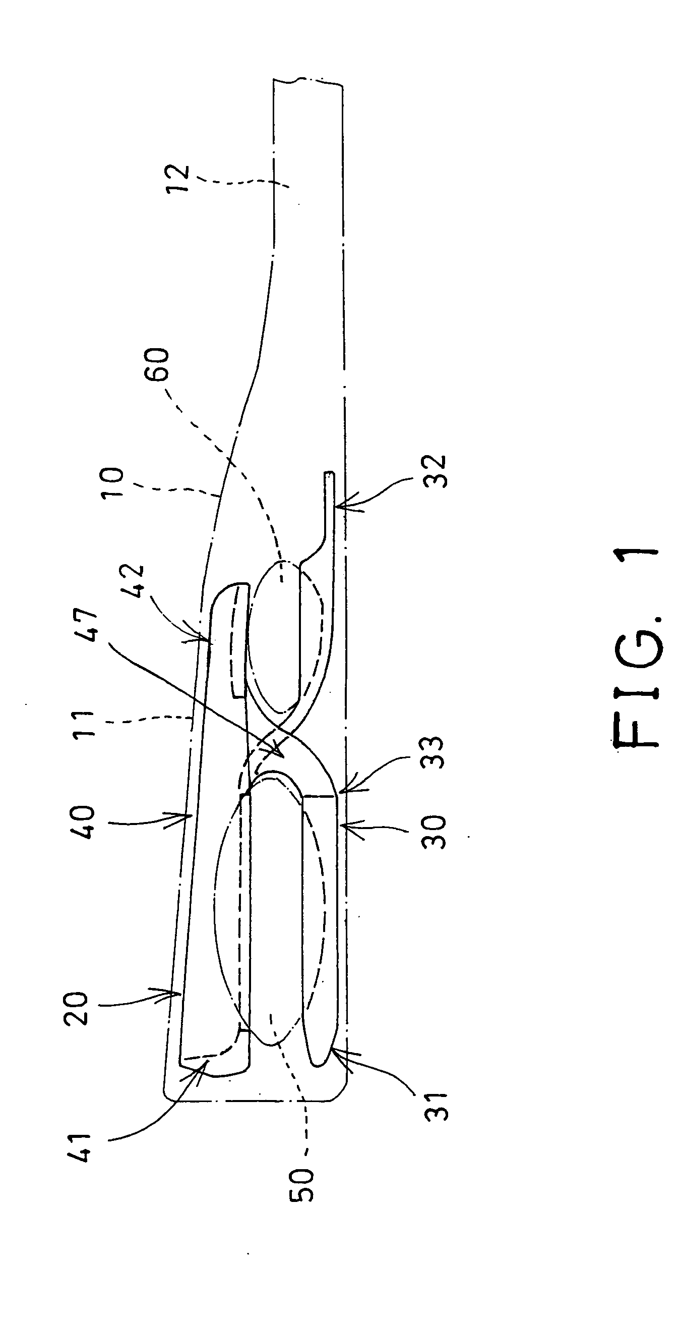
[0018] Referring to the drawings, and initially to FIG. 1, a shoe sole 10 in accordance with the present invention comprises a rear or heel portion 11 for supporting heel portions of users, a front portion 12 for supporting front foot portions of the users, and a resilient cushioning device 20 attached or engaged in the heel portion 11 of the shoe sole 10 to effectively cushion the heel portions of the users.

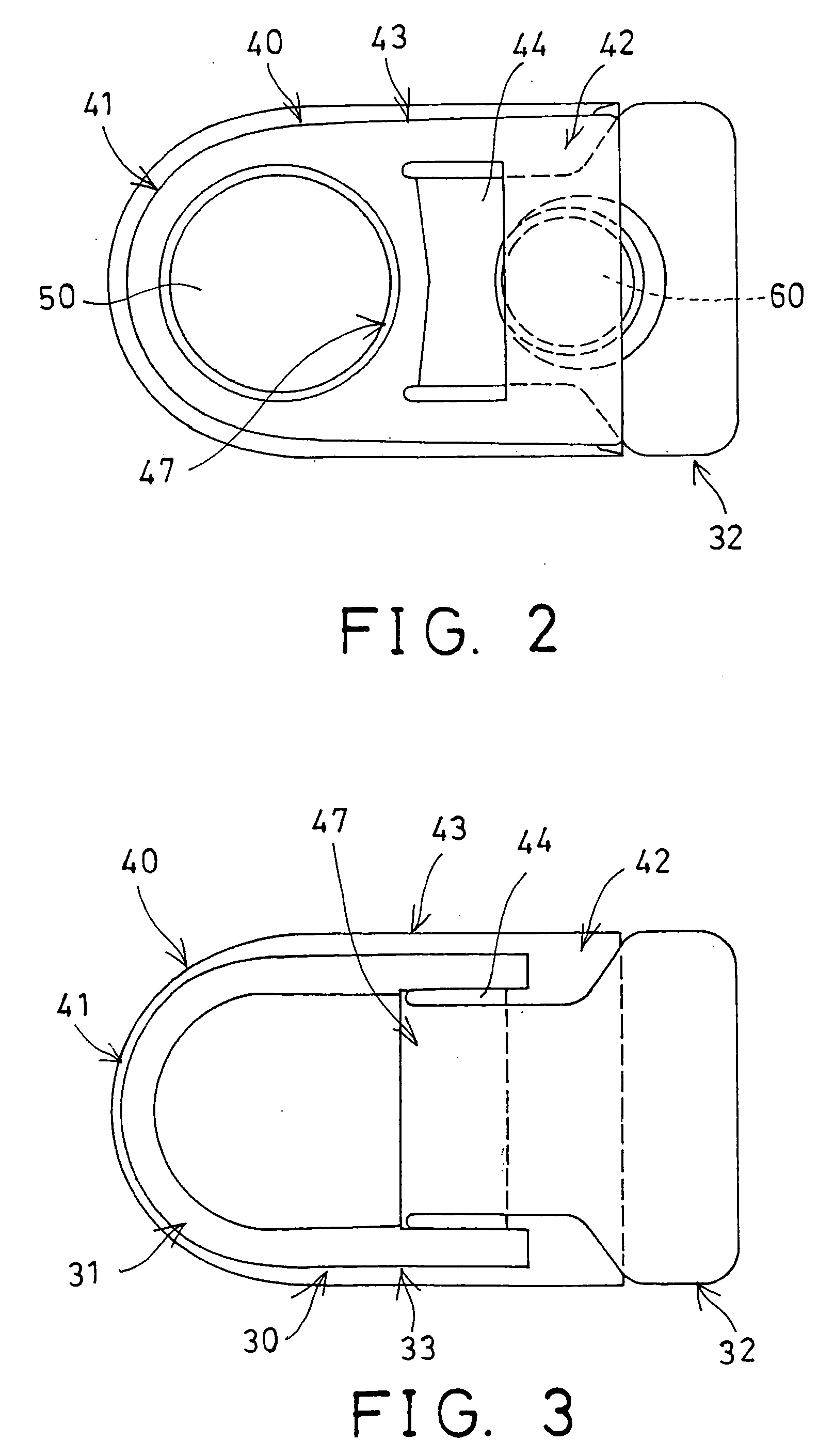
[0019] The resilient cushioning device 20 may be engaged into the heel portion 11 of the shoe sole 10 while molding the shoe sole 10, and includes two frame members 30, 40 arranged cross to each other, in order to form a substantially I or Z-shape structure (FIGS. 1, 4, 5) as seen from the side portion of the resilient cushioning device 20.

[0020] The first or the lower frame member 30 is located below the other or the upper frame member 40. Each of the frame members 30, 40 includes a rear portion 31, 41, a front portion 32, 42, and an intermediate portion 33, 43; in which the ...


PUM


Abstract

A shoe sole includes a resilient cushioning device engaged in the heel portion for cushioning heel portions of users, the resilient cushioning device includes one frame member resiliently supported above another frame member, and suspended in the shoe sole, to provide a resilience to cushion and support the heel portions of the users. A resilient member may be engaged between rear portions of the frame members, to cushion the rear portion of the lower frame member. Another resilient member may be engaged between front portions of the frame members to cushion the front portion of the upper frame member.

Description

BACKGROUND OF THE INVENTION [0001] 1. Field of the Invention [0002] The present invention relates to a shoe sole, and more particularly to a shoe sole having a resilient cushioning device for the heel portion thereof.[0003] 2. Description of the Prior Art [0004] Typical shoe soles may comprise one or more bladders or air chambers formed in the shoe soles, to increase the resilience of the shoe soles, and to resiliently support the heel portions of the users. [0005] However, the bladders or the air chambers formed in the shoe soles may not be used to effectively cushion the heel portions of the users. [0006] The present invention has arisen to mitigate and / or obviate the afore-described disadvantages of the conventional shoe soles. SUMMARY OF THE INVENTION [0007] The primary objective of the present invention is to provide a shoe sole including a resilient cushioning device for attaching to the heel portion thereof to effectively cushion the heel portions of the users, and thus to co...

Claims


Application Information

Patent Timeline
IPC IPC(8): A43B13/18A43B13/20
CPCA43B3/0052A43B13/20A43B13/183A43B7/144
Inventor YEN, CHAO HSIUNG
Owner YEN CHAO HSIUNG
Why Eureka
Try Eureka