Adjustable drive coupling for adjacent architectural coverings

a technology of driving coupling and adjacent architectural coverings, which is applied in the direction of curtain suspension devices, door/window protective devices, shutters/movable grilles, etc., can solve the problems of little resistance to peak torques that can occur, and achieve the effect of less cumbersome assembly and operation and relatively inexpensive production

Active Publication Date: 2008-06-26
HUNTER DOUGLAS IND BV
View PDF63 Cites 25 Cited by
  • Summary
  • Abstract
  • Description
  • Claims
  • Application Information

AI Technical Summary

Benefits of technology

[0006]Accordingly it is an object of the present invention to overcome or ameliorate at least one of the disadvantages of the prior art. It is also an object of the present invention to provide alternative structures which are less cumbersome in assembly and operation and which moreover can be made relatively inexpensively. Alternatively it is an object of the invention to at least provide the public with a useful choice.
[0007]To this end the present invention provides a force transmitting coupling for drivingly coupling winding devices of adjacent window coverings, the coupling including: a first coupling member; a second coupling member; mating engagement means on the first and second coupling members adapted to establish mating engagement between the first and second coupling member to transmit a drive force from one of the first and second coupling members to another of the first and second coupling members, wherein the second coupling member includes a hub and wherein the engaging means on the second coupling member are resiliently connected to the hub. Surprisingly it has been found that the resilient connection between the engaging means on one of the coupling members and its relevant hub effectively cushions the occurring peak torques and thereby successfully prevents any damage to the engagement means.

Problems solved by technology

While this arrangement has provided for accurate adjustment in aligning the lower blind edges of adjacent roller blinds, it has also offered little resistance against peak torques that can occur during operation of the blinds, from disturbing the adjustments made.

Method used


Image

  • Adjustable drive coupling for adjacent architectural coverings
  • Adjustable drive coupling for adjacent architectural coverings
  • Adjustable drive coupling for adjacent architectural coverings

Examples


Embodiment Construction

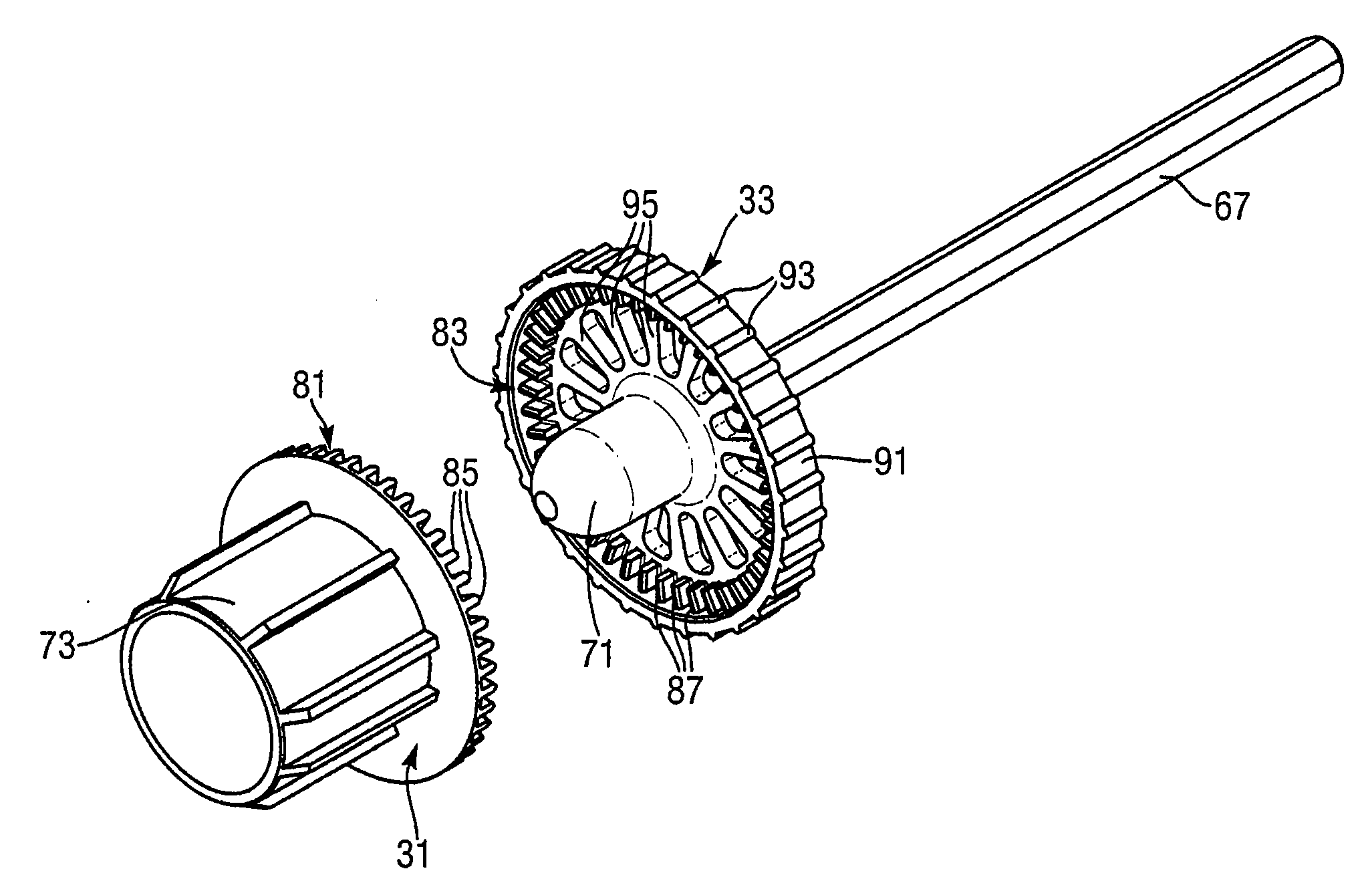
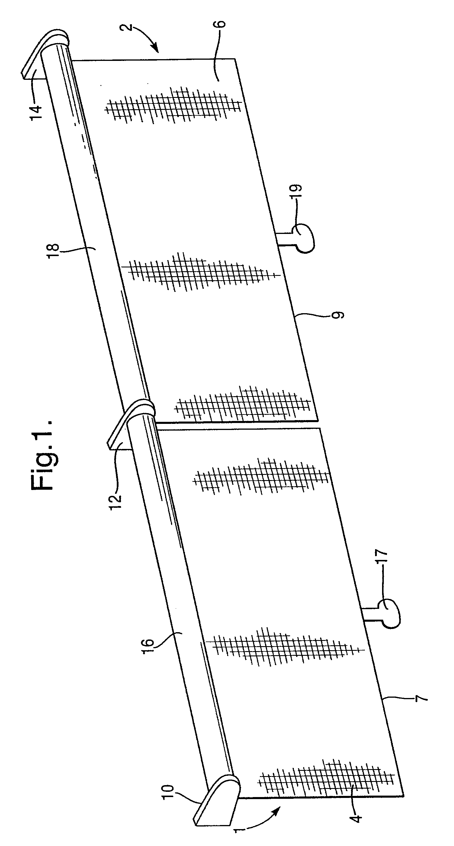
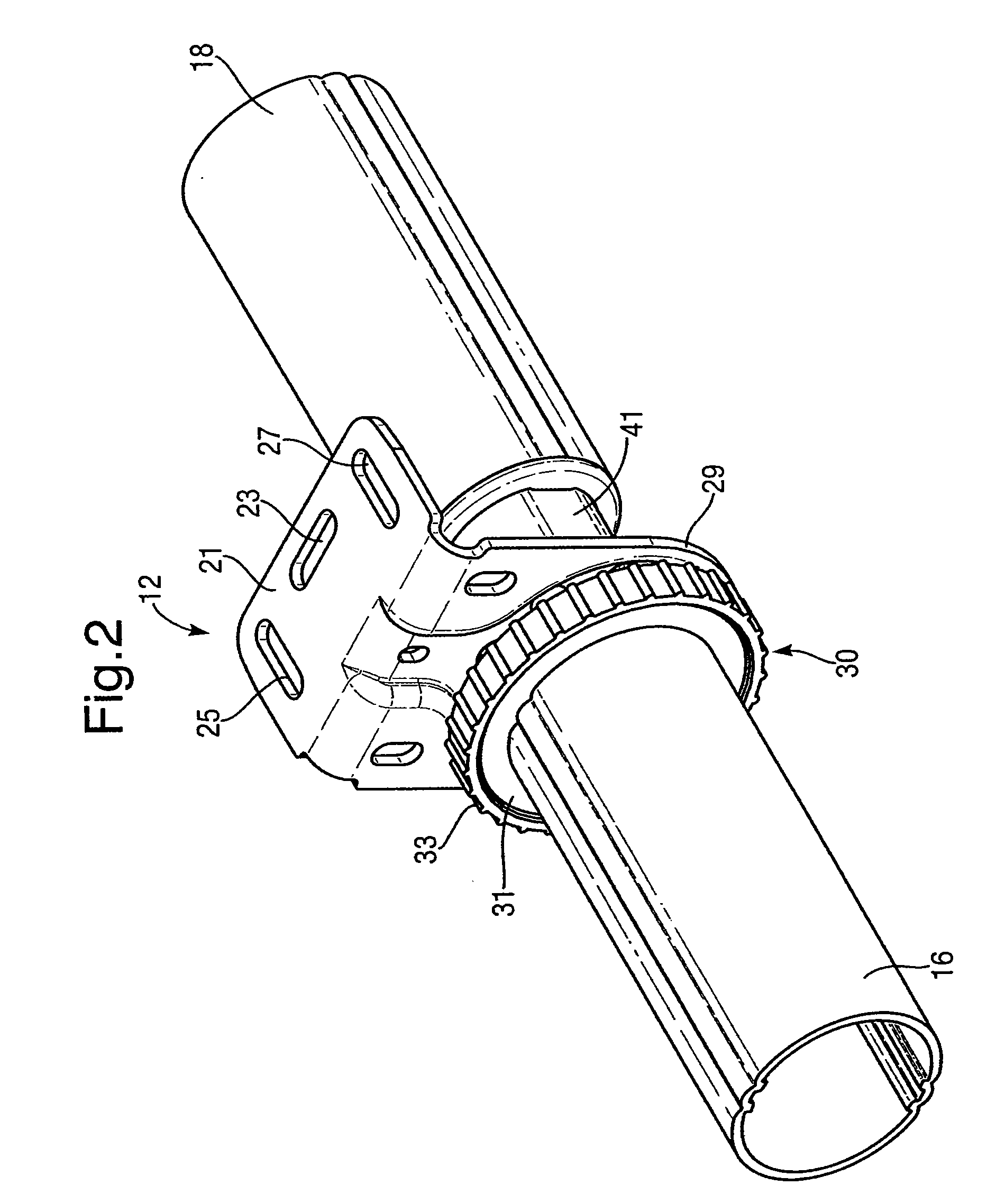
[0021]FIG. 1 shows a first window covering in the form of a first roller blind 1 and an adjacent second window covering also in the form of a second roller blind 2. The first roller blind 1 has a first winding device or blind roller 16 with its ends rotatably mounted between a left-hand end mounting bracket 10 and an intermediate mounting bracket 12. The second roller blind 2 has its winding device or second blind roller 18 rotatably mounted between the intermediate bracket 12 and a right-hand end mounting bracket 14. As is conventional the mounting brackets 10, 12, 14 serve to mount the roller blinds to a wall or ceiling surface (not shown). The roller blind 1 has a first shade member 4, shown partly rolled up on a winding device, such as a usually tubular blind roller 16. Similar, roller blind 2 as a second shade member 6 that is also partially rolled up on another winding device such as a usually tubular blind roller 18. While the window coverings shown are roller blinds it is al...


PUM


Abstract

A force transmitting coupling for drivingly coupling winding devices of adjacent architectural coverings. The coupling includes first coupling member, a second coupling member, and mating engagement means on the first and second coupling members adapted to establish mating engagement between the first and second coupling member to transmit a drive force from one of the first and second coupling members to another of the first and second coupling members. The second coupling member includes a hub and the engaging means on the second coupling member are resiliently connected to the hub.

Description

CROSS REFERENCE TO RELATED APPLICATION[0001]This application claims priority to European Application No. 06026520.4, filed 21 Dec. 2006, and such application is hereby incorporated by reference as if fully disclosed herein.BACKGROUND OF THE INVENTION[0002]1. Field of the Invention[0003]The present invention relates to a coupling for drivingly coupling winding devices of adjacent architectural coverings. More in particular the invention relates to such force transmitting couplings that include a first coupling member, a second coupling member and engagement means between the first and second coupling members adapted to provide angular adjustment between the winding devices of the two adjacent architectural coverings.[0004]2. Description of the Relevant Art[0005]It has been proposed in WO 2006 / 102894 to obtain angular fine adjustment between blind rollers by providing a wrap spring coupling between the two blind rollers, which normally is in frictional engagement, but which can be dis...

Claims


Application Information

Patent Timeline
Patent Type & Authority Applications(United States)
IPC IPC(8): F16D3/00
CPCF16D7/044E06B2009/1746
Inventor KOOP, LARSBOHLEN, JORG
Owner HUNTER DOUGLAS IND BV
Why Eureka
Try Eureka